
Router Installation Guide

1-13
Cisco XR 12410 Router Installation Guide
OL-13832-01
Chapter 1 Cisco XR 12410 Router Overview
Line Card and Route Processor Overview
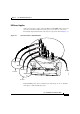
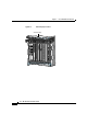
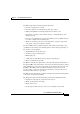
The following connectors and LEDs are on the front panel of the alarm display
(
Figure 1-8):
Figure 1-8 Alarm Display
• Cable connections for the two alarm cards (labeled Alarm A and Alarm B)
• Critical, Major, and Minor LEDs that identify system level alarm conditions
• A pair of status LEDs that correspond to each of the 9 card slots in the switch
fabric and alarm card cage (seven fabric cards and two alarm cards):
–
ENABLED (green)
On—The card installed in that slot is operational and functioning
properly.
Off—Either the slot is empty or the card installed in that slot is faulty.
–
FAIL (yellow)—The card in that slot is faulty.
Line Card and Route Processor Overview
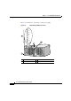
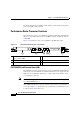
The line card and route processor (RP) card cage has 10 user-configurable slots
that support a combination of line cards and either one or two RPs (see
Figure 1-2). Router configurations can consist of either nine line cards and one
RP, or eight line cards and two RPs (one primary and one redundant) using the
following slot configurations:
• Slots 0 to 7 accommodate the newer (wider) line card designs. These wider
line card slots can also accept narrower legacy line cards.
• Slots 8 and 9 only accept RPs or a narrower legacy line card.
Note If a system uses only one RP install it in slot 9. You can use slot 8 for a
legacy line card.
ALARM A
ALARM B
A
A
MBUS
M
IN
O
R
B
FAI L
ENABLE
M
A
JO
R
C
R
IT
IC
A
L
B
0
CSC
1
0
SFC
1
23
4
53368