
Router Installation Guide

Chapter 5 Maintaining the Router
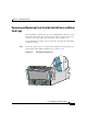
Removing and Installing a Chassis
5-42
Cisco XR 12410 Router Installation Guide
OL-13832-01
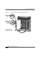
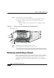
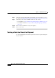
Step 2 Remove the card (a CSC in this example):
a. Pivot the ejector levers to unseat the card from the backplane connector.
b. Grasp the card by its metal card carrier and slide the card out of the
slot
(Figure 5-25).
–
Place the card directly into an antistatic bag or other ESD-preventive
container.
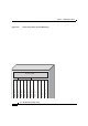
Figure 5-25 Removing a Card from the Switch Fabric and Alarm Card Cage
Step 3 To install the card, reverse the procedure in Step 2.
Step 4 Close the air filter door and tighten the captive screws.
Removing and Installing a Chassis
This section provides the procedures to remove and replace a chassis. You may
need to perform this procedure to replace a defective chassis or move it to another
location. These instructions include the steps directing you to removal and
replacement instructions for individual components such as power supplies and
line cards.
ALARM
2
S
F
C
53270
Air filter door
-3/STM-POS
6DS3–SMB P
/
H
/
F
12DS3–SMB P
/
H
/
F
-48/STM-16-SCPOS
OC-12/STM-4 ATM
ST ETERNET
E PROCESSOR
Clock scheduler card