
Router Installation Guide

Chapter 5 Maintaining the Router
Removing and Replacing AC and DC Power Subsystem Components
5-22
Cisco XR 12410 Router Installation Guide
OL-13832-01
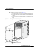
Step 7 Install the rear chassis components (see Figure 5-12):
a. Install the new AC PDU and tighten the (4) screws to secure it to the chassis.
b. Replace the rear panel and tighten the (16) captive screws.
Note The rear panel has a lip that fits over the top of the chassis. Be sure to fit
the bottom of the rear panel above the AC horizontal trough.
c. Replace the AC horizontal trough and tighten the (6) captive screws.
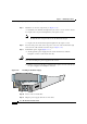
Step 8 Reconnect the power cable to the AC power connector on the horizontal trough
and secure the cable with the retention clip (see
Figure 5-11).
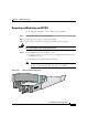
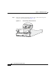
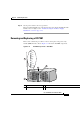
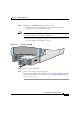
Step 9 Reinstall the power supply (Figure 5-13):
a. Slowly push the power supply into the chassis until it mates with the
backplane connector at the back of the bay.
Caution To prevent damage to the power shelf backplane connector, do not use excessive
force when inserting the power supply into the chassis.
b. Lift the ejector lever into place and tighten the captive screw to securely seat
the power supply to the backplane connector.
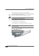
Figure 5-13 Installing an AC Power Supply
Step 10 Power on the circuit breaker.
Step 11 Plug the power supply cable into its AC outlet.
93228
0
PWR OK
FAULT
TEMP
ILIM
0
PW
R O
K
FAULT
TEM
P
ILIM