
Router Installation Guide

Chapter 4 Troubleshooting the Installation
Troubleshooting Overview
4-4
Cisco XR 12410 Router Installation Guide
OL-13832-01
Identifying Startup Issues
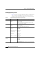
Table 4-1 shows the contents of the alphanumeric displays on the RP and the line
cards, as well as the normal LED states on the alarm card, the power entry
modules (AC or DC), and the blower module after a successful system startup.
Ta b l e 4-1 Alphanumeric Displays and LEDs at System Startup
Component Type of Indicator Display Contents/LED Status and Meaning
RP Alphanumeric
display
Top row: MSTR
Bottom row: PRP
The RP is enabled and recognized by the system; a valid
Cisco software image is running.
Line Cards Alphanumeric
display
Top row: IOS XR
Bottom row: RUN
The line card is enabled and ready for use.
Alarm Display Detected alarm
severity
MBUS (Alarm A and
Alarm B cards)
CSC 0 and 1
SFC 0, 1, 2, 3, and 4
Critical: Off
Major: Off
Minor: Off
Enabled: On
Fail: Off
Enabled: On
Fail: Off
Enabled: On
Fail: Off
AC Power
Supplies
Power status Pwr OK: On
Fault: Off
Temp: Off
Ilim: Off
The correct power module voltages are present and no faults
have been detected.