
Router Installation Guide

3-35
Cisco XR 12410 Router Installation Guide
OL-13832-01
Chapter 3 Installing the Cisco XR 12410 Router
Connecting Line Card Network Interface Cables
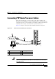
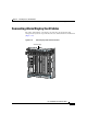
Use the following procedure as an example to route the network interface cables
through the cable-management system and connect them to the line card.
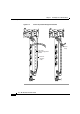
Step 1 Route an interface cable across the horizontal cable-management tray, through the
cable tray opening to connect it to the line card:
• For legacy fiber-optic line cards, go to Step 2.
• For current fiber-optic line cards, go to Step 6.
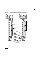
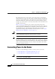
Step 2 Install a plastic bend-radius clip on the strain-relief ferrule on the connector (see
blow-out in
Figure 3-26).
Note The bag of bend-radius clips (Part Number 800-06119-01) in the
accessories box that shipped with your router contains two sizes of
bend-radius clips. The clip size is determined by the diameter of the
strain-relief ferrule on the cable connectors. Use the size that provides the
most secure fit on the strain-relief ferrule on the cable connectors in use
at your site.
Step 3 Insert the cable connector into its assigned port.
Step 4 Route the cable up the cable-management bracket and carefully press the cable
into the channel so it is held in place by the cable clips (
Figure 3-26b).
Step 5 Repeat Steps 3 through 5 for each additional cable connection to that line card.