
Router Installation Guide

1-23
Cisco XR 12406 Router Installation Guide
OL-13831-01
Chapter 1 Cisco XR 12406 Router Overview
Line Cards
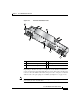
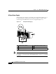
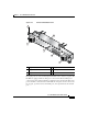
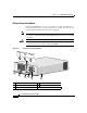
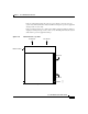
A DC-input PEM (shown in Figure 1-9) has the following features:
• A circuit breaker switch on the faceplate turns the PEM on and off.
• A handle is provided for ease in removing and replacing the PEM.
• Captive screws on the PEM ejector levers secure it in the PEM bay.
• Three LEDs on the faceplate to provide status information. Table 1-2
summarizes the function of these indicators.
• Each PEM weighs 10.5 pounds (4.76 kg), and can deliver up to 1400 W at
-48 VDC.
• Each PEM requires a hardwired source DC power cable from the site DC
power source to the DC PDU in the router. The DC power cable leads to the
PDU should be #6 American Wiring Gauge (AWG) high-strand-count wires.
• Only a DC power source that complies with the safety extra-low voltage
(SELV) requirements in UL1950, CSA 950, EN 60950, and IEC950 can be
connected to a PEM.
• The router requires a dedicated 45A DC circuit breaker for the DC power
source. This circuit breaker should protect against short-circuit and
overcurrent faults in accordance with United States National Electrical Code
NFPA 70 (United States), Canadian Electrical Code, part I, CSA C22.1
(Canada), and IEC 364 (other countries).
Note We recommend that you install an uninterruptable power source (UPS) as
a safeguard against power loss.
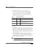
Table 1-2 DC-input PEM LED Indicators
LED Label Color Function
OUTPUT OK Green PEM is operating normally in a powered-on
condition.
INPUT OK Green DC power is present at the PEM input and
within the specified limits.
MISWIRE Amber Indicates input is wired backward at the PDU
input.