
Router Installation Guide

1-13
Cisco XR 12406 Router Installation Guide
OL-13831-01
Chapter 1 Cisco XR 12406 Router Overview
Line Cards
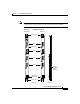
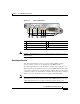
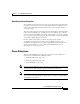
Figure 1-5 Alarm Card Features
Note The Cisco XR 12406 Router must be populated with two alarm cards, to meet
EMI standards.
Alarm Output Function
The alarm output function consists of a group of relays, LEDs, and their
associated drivers connected to an output port on the MBus module.
The alarm output function is controlled by the software on the route processor.
When a signal is received from the route processor, the MBus module on the alarm
card activates specific relays to signal an alarm condition. There are three alarm
condition severity levels: critical, major, and minor. The critical, major, and minor
LEDs are paired for redundancy to protect against a single failed LED.
Note Alarm cards for some Cisco XR 12000 series router have both audible and visible
alarm indicators. The alarm card for the Cisco XR 12406 Router provides only
visible alarm indicators as local alerts to unusual conditions in the router.
1 MBus status LED 5 Major alarm LED
2 CSC status LEDs (two) 6 Minor alarm LED
3 SFC status LEDs (three) – Alarm relay contact connector
4 Critical alarm LED —
MBUS
CSC
ENABLED
FAIL
ALARM
0
SFC
CRITICAL
MAJOR
MINOR
01 1 2
1 432 5 6
66170