
Router Installation Guide


5-57
Cisco XR 12406 Router Installation Guide
OL-13831-01
Chapter 5 Maintaining the Router
Removing and Installing a Clock and Scheduler Card, Switch Fabric Card, or Alarm Card
Verifying the Installation of Alarm Cards, Clock Scheduler Cards, and Switch
Fabric Cards
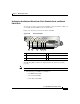
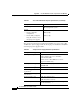
To verify proper router operation after installing a replacement CSC or SFC, you
can visually check the LEDs on the two alarm cards.
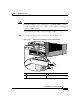
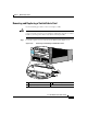
Figure 5-35 shows the location of the alarm card LEDs.
Figure 5-35 Alarm Card LEDs
The following LED conditions are displayed when the system is operating
properly:
Note Green = Enabled, amber = Fail
• The following green LEDs are normally on:
–
The MBUS status LED
–
Two CSC status LEDs
–
Three SFC status LEDs
1 MBus status LED 4 Critical alarm LED
2 CSC status LEDs (two) 5 Major alarm LED
3 SFC status LEDs (three) 6 Minor alarm LED
MBUS
CSC
ENABLED
FAIL
ALARM
0
SFC
CRITICAL
MAJOR
MINOR
01 1 2
1 432 5 6
66170