
Router Installation Guide

Chapter 4 Troubleshooting the Installation
Troubleshooting the Processor Subsystem
4-22
Cisco XR 12406 Router Installation Guide
OL-13831-01
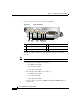
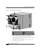
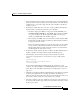
Figure 4-5 shows the location of the alarm card LEDs.
Figure 4-5 Alarm Card LEDs
The following LED conditions are displayed when the system is operating
properly:
Note Green = ENABLED, amber = FAIL
• The following green LEDs are normally on:
–
The MBUS status LED
–
Two CSC status LEDs
–
Three SFC status LEDs
• The following amber LEDs are normally off:
–
The MBUS status LED
–
Two CSC status LED
–
Three SFC status LEDs
• The three amber router alarm (CRITICAL, MAJOR, MINOR) LEDs are
normally off.
1 MBus status LED 4 Critical alarm LED
2 CSC status LEDs (two) 5 Major alarm LED
3 SFC status LEDs (three) 6 Minor alarm LED
MBUS
CSC
ENABLED
FAIL
ALARM
0
SFC
CRITICAL
MAJOR
MINOR
01 1 2
1 432 5 6
66170