
Router Installation Guide

4-19
Cisco XR 12406 Router Installation Guide
OL-13831-01
Chapter 4 Troubleshooting the Installation
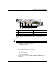
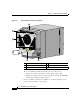
Troubleshooting the Processor Subsystem
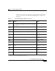
During the line card boot process, which occurs immediately after the RP boot
process, you can observe the alphanumeric LED displays on each line card
(Table 4-5).
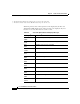
Table 4-5 Line Card LED Display, Definition, and Source
LED
Display
1
1. The LED sequence shown in Table 4-5 might occur too quickly for you to view. The sequence in this table is provided as an
example of how the line cards should function at startup.
Definition Source
MROM
nnnn
MBus microcode begins to execute; nnnn is the microcode
version number. For example, microcode version 1.17 would
display as 0117.
2
MBus controller
LMEM
TEST
Low memory on the line card is being tested. Line card ROM monitor
MEM
INIT
Main memory on the line card is being discovered. Line card ROM monitor
ROMI
GET
ROM image is being loaded into line card memory. RP Cisco IOS XR
software
FABL
WA I T
Line card is waiting for the fabric downloader to load.
3
RP Cisco IOS XR
software
FABL
DNLD
Fabric downloader is being loaded into line card memory. RP Cisco IOS XR
software
FABL
STRT
Fabric downloader is being launched. RP Cisco IOS XR
software
FABL
RUN
Fabric downloader has been launched and is running. RP Cisco IOS XR
software
IOS
DNLD
Cisco IOS XR software is being downloaded into line card
memory.
RP Cisco IOS XR
software
IOS
STRT
Cisco IOS XR software is being launched. RP Cisco IOS XR
software
IOS
UP
Cisco IOS XR software is running. RP Cisco IOS XR
software
IOS
RUN
Line card is enabled and ready for use. RP Cisco IOS XR
software