
Router Installation Guide

Chapter 4 Troubleshooting the Installation
Troubleshooting a DC Power Subsystem
4-10
Cisco XR 12406 Router Installation Guide
OL-13831-01
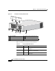
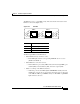
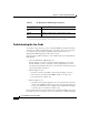
Figure 4-2 DC-Input Power Entry Module LEDs
Table 4-2 summarizes the function of these indicators.
1 DC-input PEM 4 Captive screws on release levers
2 Handle 5 Air inlet for cooling fan
3 ON/OFF circuit breaker switch —
62203
O
U
T
P
U
T
O
K
I
N
P
U
T
O
K
M
I
S
W
I
R
E
OUTPUT
OK
INPUT
OK
MISWIRE
1
2
4
5
4
3
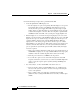
Table 4-2 DC-Input PEM LED Indicators
LED Label Color Function
OUTPUT OK Green PEM is operating normally in a powered-on
condition.
INPUT OK Green DC power is present at the PEM input and
within the specified limits.
MISWIRE Amber Indicates input is wired backward at the
PDU input.