
Router Installation Guide


Chapter 4 Troubleshooting the Installation
Troubleshooting an AC Power Subsystem
4-6
Cisco XR 12406 Router Installation Guide
OL-13831-01
Troubleshooting an AC Power Subsystem
AC PEMs provide –48 VDC OUTPUT. The +5 VDC OUTPUT from the CSF
powers the MBus module on each card in the system. The MBus module, in turn,
control the DC-DC converters also present on each card in the system. The
DC-DC converter takes –48 VDC from the power supply and converts it into +2.5,
+3.3 and +5 VDC, which is distributed to the card circuitry.
AC PEMs are monitored by the MBus module and the RP for over- or
undervoltage and over- or undercurrent conditions.
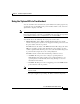
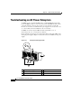
Begin checking the AC-input power subsystem by first looking at the LEDs on the
AC-input power supplies. Figure 4-1 shows the location of the LEDs on the power
supply.
Figure 4-1 AC-Input Power Supply LEDs
1 AC-input power supply 4 Captive screws on release levers
2 Handle 5 LEDs
3 Power standby switch – –
57916
1
3
2 5
4