
Router Installation Guide


Chapter 3 Installing the Cisco XR 12406 Router
Powering On the Router—First Time
3-32
Cisco XR 12406 Router Installation Guide
OL-13831-01
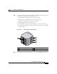
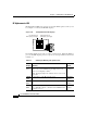
Step 6 Visually check the LEDs on the two alarm cards (Figure 3-17):
LEDs that normally should be off:
• One MBUS status LED labeled FAIL
• Two CSC status LEDs labeled FAIL
• Three SFC status LEDs labeled FAIL
• Three router alarm LEDs labeled CRITICAL, MAJOR, MINOR
LEDs that normally should be on:
• One MBUS status LED labeled ENABLED
• Two CSC status LEDs labeled ENABLED
• Three SFC status LEDs labeled ENABLED
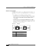
Figure 3-17 Alarm Card LEDs On/Off Conditions
Step 7
On the console terminal, verify that the console displays the system banner and
that the system and all interfaces initialize successfully.
1 MBus status LED 4 Critical alarm LED
2 CSC status LEDs (two) 5 Major alarm LED
3 SFC status LEDs (three) 6 Minor alarm LED
MBUS
CSC
ENABLED
FAIL
ALARM
0
SFC
CRITICAL
MAJOR
MINOR
01 1 2
1 432 5 6
66170