
Router Installation Guide

Chapter 3 Installing the Router
Connecting to a DC Power Source
3-27
Cisco XR 12404 Router Installation Guide
OL-13830-02
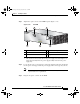
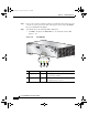
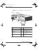
Step 6 Secure each lead to the proper terminal port by tightening the terminal port
connector screws with a 3/16-inch flat-blade screw driver (Figure 3-16).
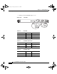
Figure 3-16 DC PDU Power Block
Step 7
Verify that the DC power source circuit breaker servicing the DC PEM is
switched on.
1 Negative Terminal Port 3 Ground Terminal Port
2 Positive Terminal Port 4 Terminal Port Connector Screws
66949
+
GND
1
4
2
3
todd.book Page 27 Tuesday, July 24, 2007 3:54 PM