
Router Installation Guide


3-10
Cisco XR 12404 Router Installation Guide
OL-13830-02
Chapter 3 Installing the Router
Supplemental Bonding and Grounding Connections
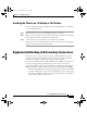
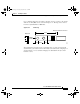
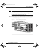
Use a cable lug with two holes at 0.63" (16 mm) centers to connect to the chassis
with two 6.3 mm (M6) screws as shown in Figure 3-4. The lug can be ordered
from Cisco (Part Number 32-0607-01).
Figure 3-4 Cable Lug
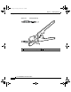
The dual-hole lug is crimped onto a grounding wire of a wire size and length
determined by your router location and facility environment. The crimping tool
shown in Figure 3-5 is a standard crimping tool obtainable from any normal
hardware source.
Crimp area
25527
2.24
0.48
0.08
0.25 0.370.63
End View
Ø 0.267
2 holes
All measurements in inches
todd.book Page 10 Tuesday, July 24, 2007 3:54 PM