
Router Installation Guide


1-19
Cisco XR 12404 Router Installation Guide
OL-13830-02
Chapter 1 Cisco XR 12404 Router Overview
Power Entry Modules
DC PEMs
Each DC PEM operates from a nominal source DC voltage of -48 to -60 VDC and
requires a dedicated 60 amp service.
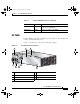
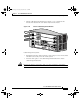
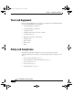
Figure 1-9 identifies the components of a DC power supply.
Figure 1-9 DC PEM and PDU Components
Input OK Green The AC power source is present and operating
within the specified limit.
Output Fail Amber Indicates a failure in the PEM.
Table 1-4 AC-Input PEM LED Indicators (continued)
LED Label Color Function
1 DC PDU 5 On/Off switch
2 DC PEM 6 PDU captive screws
3 PEM captive screws 7 PDU terminal block
4 Status LEDs
I
N
P
U
T
–
4
8
/
6
0
V
3
5
A
66295
IN
P
U
T
O
K
O
U
T
P
U
T
F
A
IL
O
U
T
P
U
T
O
K
5
6
4
3
7
1 2 3
todd.book Page 19 Tuesday, July 24, 2007 3:54 PM