
Router Installation Guide

5-25
Cisco XR 12404 Router Installation Guide
OL-13830-02
Chapter 5 Maintaining the Router
Removing and Replacing a DC PDU
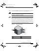
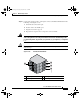
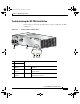
Step 10 Connect the ground, positive, and negative wires to the PDU terminal block in the
following order (Figure 5-15):
a. Ground lead to the bottom port.
b. Positive lead to the middle port.
c. Negative lead to the top port.
d. Repeat these steps for the second power connector block.
Warning
To prevent injury and damage to the equipment, always attach the ground and
source DC power leads to the power block connector in the following order:
(a) ground to ground, (b) positive (+) to positive (+), (c) negative (–) to negative
(–).
Caution Be sure to connect the wires according to the color coding notes and labels you
made in Step 3.
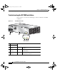
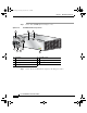
Figure 5-15 DC PDU Terminal Block
1 Negative port 3 Ground port
2 Positive port 4 Terminal port connector screws
66949
+
GND
1
4
2
3
todd.book Page 25 Tuesday, July 24, 2007 3:54 PM