
Router Installation Guide

Chapter 5 Maintaining the Router
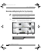
Removing and Replacing an AC Power Entry Module
5-14
Cisco XR 12404 Router Installation Guide
OL-13830-02
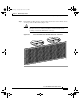
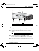
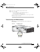
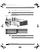
Figure 5-8 AC PEM Components
Tip If you plan to return the defective PEM to the factory, repackage it in the shipping
container you received with the replacement PEM.
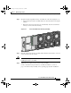
Step 7 Slide the replacement PEM into the bay until it is seated to the backplane
connector.
Note Make sure the power switch is in the off (0) position.
Step 8 Tighten the two captive screws to secure the PEM to the chassis.
Electrical connections between the PEM the backplane connector are made
automatically when the PEM is fully seated and the captive screws are tightened.
Step 9 Connect the power cord into the receptacle and place the bail latch over the power
cord to secure it in place.
Step 10 Plug the power cord into its AC outlet.
1 AC PEM finger grips 4 Power cord receptacle
2 On/Off switch 5 Status LEDs
3 Bail latch 6 Captive screws
IN
PU
T
O
K
O
U
TP
UT
F
AIL
I
N
P
U
T
1
0
0
-
2
4
0
V
1
2
A
5
0
/
8
0
H
Z
O
U
TP
U
T
O
K
66289
456
1
2 3
todd.book Page 14 Tuesday, July 24, 2007 3:54 PM