
Router Installation Guide

Chapter 4 Troubleshooting the Installation
Troubleshooting the DC Power Subsystem
4-10
Cisco XR 12404 Router Installation Guide
OL-13830-02
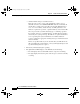
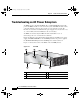
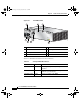
Figure 4-2 DC PEM and PDU
Table 4-2 summarizes the function of these indicators.
1 DC PDU 5 On/Off switch
2 DC PEM 6 PDU captive screws
3 PEM captive screws 7 Terminal Block
4 LEDs
INPUT
– 48/60V
35A
66295
IN
P
U
T
O
K
O
U
T
P
U
T
F
A
I
L
O
U
T
P
U
T
O
K
5
6
4
3
7
1 2 3
Table 4-2 DC-Input PEM LED Indicators
LED Label Color Function
OUTPUT OK Green PEM is operating normally in a powered-on
condition.
INPUT OK Green DC power is present at the PEM input and
within the specified limits.
OUTPUT FAIL Amber Indicates a failure in the PEM.
todd.book Page 10 Tuesday, July 24, 2007 3:54 PM