Cisco XR 12000 Series Router Ethernet Line Card Installation December 10, 2008 Document Part Number: OL-7861-01 This guide contains instructions for installing Ethernet line cards in supported Cisco XR 12000 Series Routers. Also included are basic troubleshooting techniques to help in line card installation.
Important Information Important Information This section contains information about the following topics: • Ethernet Line Card Product Numbers, page 2 • Router Hardware Installation, page 2 • Cisco IOS Software Release and Hardware Revision Requirements, page 3 • Memory Options, page 4 • Related Documentation, page 4 Ethernet Line Card Product Numbers Table 1 lists the Cisco product numbers to which this publication applies.
Important Information Note The Cisco XR 12000 Series Routers must have a full set of switch fabric cards installed to support the requirements of the Ethernet line cards. See the appropriate Cisco 12000 Series Router installation guide for information about the switch fabric and other related requirements. Note Because the 10-Port 1-Gigabit Ethernet, 1-Port 10-Gigabit Ethernet, and Modular Gigabit Ethernet line cards require a card cage slot that is 1.8 inches (4.
Product Overviews Memory Options Ethernet line card memory options vary by line card. See “Line Card Memory” section on page 65 for more information. Related Documentation This publication describes the basic installation of a Ethernet line card. For complete configuration information, refer to the following publications: • Cisco IOS XR Interface and Hardware Component Configuration Guide, Release 3.2 • Cisco IOS XR Interface and Hardware Component Command Reference, Release 3.
Product Overviews Table 4 Ethernet Line Card 1-Port 10-Gigabit Ethernet Ethernet Line Card Hardware Comparison (continued) Line Card Part Number 1X10GE-LR-SC= (LR laser optical transceiver) 1X10GE-ER-SC= (ER laser optical transceiver) Ports GBIC SFP Pluggable Pluggable Insertable EPA Daughter Card Cable and Connector 1 Single-mode fiber with SC connectors 1 Single-mode fiber with SC connectors Caution To prevent system problems, do not use Gigabit Interface Converters (GBICs) from third-party
Product Overviews 1 Ejector lever (one at each end) 3 Alphanumeric LEDs 2 Status LEDs (one set per port) 4 Port (provided by SFP module) Table 5 summarizes the optics and connectors used by the 4-Port Gigabit Ethernet ISE line card. Table 5 4-Port Gigabit Ethernet ISE Line Card Optics and Connector Types Part Number Optics/Transmission Maximum Distance Connector Type 4GE-SFP-LC See Table 14 on page 49. See Table 14 on page 49.
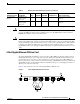
Product Overviews 0 1 2 3 4 5 6 7 8 98892 RX FRAME ACTIVE 10-Port 1-Gigabit Ethernet Line Card LINK Figure 2 9 10X1GE-SFP-LC LINK ACTIVE RX FRAME 3 0 1 2 1 SFP module receptacle 2 Port status LEDs 3 Alphanumeric LEDs Table 6 summarizes the optics and connectors used by the 10-Port 1-Gigabit Ethernet line card.
Product Overviews 1-Port 10-Gigabit Ethernet Line Card The 1-Port 10-Gigabit Ethernet line card provides the supported Cisco XR 12000 Series Routers with one optical 802.3ae 10-Gigabit Ethernet interface. This interface provides a high-speed connection to other network devices, such as Cisco XR 12000 Series Routers, or to other routers or layer-2 or layer-3 switches that support 10-Gigabit Ethernet interfaces. Figure 3 shows the front view of the line card.
Preparing for Installation Preparing for Installation The following sections provide information about preparing to install line cards: • Safety Guidelines, page 9 • Preventing Electrostatic Discharge, page 9 • Required Tools and Equipment, page 10 Safety Guidelines Before you perform any procedure in this publication, review the safety guidelines in this section to avoid injuring yourself or damaging the equipment. The following guidelines are for your safety and to protect equipment.
Removing and Installing a Line Card • Warning Avoid contact between the Ethernet line cards and clothing. The wrist strap protects the board from ESD voltages on the body only; ESD voltages on clothing can still cause damage. For safety, periodically check the resistance value of the ESD strap. The measurement should be between 1 and 10 megohms.
Removing and Installing a Line Card Guidelines for Line Card Removal and Installation Guidelines for line card removal and installation include the following: • Online insertion and removal (OIR) is supported, enabling you to remove and install line cards while the router is operating. OIR is seamless to users on the network, maintains all routing information, and ensures session preservation. With OIR, notifying the software or resetting the power is not required.
Removing and Installing a Line Card Step 2 Disconnect and remove all interface cables from the ports; note the current connections of the cables to the ports on the line card. Step 3 Detach the line card cable-management bracket from the line card. Step 4 Use a screwdriver to loosen the captive screw at each end of the line card faceplate. (See Figure 4a.
Removing and Installing a Line Card Caution Note Be careful not to damage or disturb the EMI spring fingers located on the front edge of the card face plate. Always insert a dust plug in an optical port opening for each port that is not in use. For information on disconnecting interface cables, see the “Removing and Installing Fiber-Optic Interface Cables” section on page 52.
Removing and Installing a Line Card Figure 5 Ejector Levers H7681 When inserting a card, make sure the ejector lever hooks catch the lip of the card cage. Caution When you install a line card, always use the ejector levers to ensure that the card is correctly aligned with the backplane connector, the card connector pins make contact with the backplane in the correct order, and the card is fully seated in the backplane.
Removing and Installing EPAs For information on verifying and troubleshooting the hardware installation, see the “Verifying and Troubleshooting the Installation” section on page 58. Removing and Installing EPAs The Modular Gigabit Ethernet line card ships with 0, 1, 2, or 3 EPAs installed.
Removing and Installing EPAs To remove an EPA from your Modular Gigabit Ethernet line card, use Figure 7 on page 17 as a reference and follow these steps: Step 1 Attach an ESD-preventive wrist or ankle strap and follow its directions for use. Step 2 Disconnect the LC-type fiber-optic cable connector from the SFP module. Note which cable connector plug is TX and which is RX for reattachment. Step 3 Insert a dust plug into the optical ports of the SFP module to keep the optical interfaces clean.
Removing and Installing EPAs Figure 7 Removing an EPA B CO TO TA LL INS PU RN ER SH S C LIF HE R TO E MO VE RE T 75548 A If the EPA bay is to remain empty, install an EPA blank (Product Number MAS-EPA-BLANK=) to keep dust out of the line card and to maintain proper airflow and EMI through the line card and chassis.
Removing and Installing EPAs Figure 8 Locations of Labels and Reference Points on the EPA ATTENTION: USE CARE DURING INSTALLATION OF EPA CARD, MIS-ALIGNMENT CAN CAUSE DAMAGE TO THE CONNECTOR AT THE UNDERSIDE REAR OF THE PCB. 129768 DO NOT APPLY EXCESSIVE FORCE TO THE FRONT PANEL OR TOP SURFACE DURING INSTALLATION OR DAMAGE CAN OCCUR TO THE PCB CONNECTOR. Caution The connectors must be engaged without any angular misalignment. Engaging the connectors at an angle will cause damage to the connectors.
Removing and Installing EPAs Step 2 Ensure that the connector guide pins are aligned, and mate the connector of the EPA to the connector on the line card, as shown in Figure 9 and Figure 10. Figure 10 shows two side views of the EPA and line card.
Removing and Installing EPAs Figure 10 Side Views - Mating the Connector of the EPA to the Line Card ˚ ˚ 4 Max 129857 20 Max Step 3 Ensure that the connector guide pins are aligned. Once the connector is engaged, apply gentle pressure with your thumbs to the two rear outer corners of the EPA, as shown in Figure 11 and Figure 12.
Removing and Installing EPAs Figure 12 Rear Outer Corners of the EPA (Close-up) PUSH PUSH BOTH CORNERS TO INSTALL BOTH CORNERS TO INSTALL PU CO BO R TH INS TO NERS TA LL SH PU Step 4 SH 129765 CO BO R TH INS TO NERS TA LL Press gently on the white labels in middle of the outer edge of the EPA as shown in Figure 13 to ensure that the connector is fully seated.
Removing and Installing EPAs Step 5 Caution Use a Phillips screwdriver to insert and tighten the screw on the EPA, 3 to 5 in-lbs, as shown in Figure 14. Apply no more than 5 in-lbs of torque when tightening the screw.
Removing and Installing GBICs Step 6 Caution Use a Phillips screwdriver to insert and tighten the two screws on the faceplate of the line card, 3 to 5 in-lbs, as shown in Figure 15. Apply no more than 5 in-lbs of torque when tightening the screw. Figure 15 Inserting the 2 screws on the Faceplate of the Line Card PUS CORN ERS TO INST ALL H PUS H 129856 CORN ERS TO INST ALL Removing and Installing GBICs Your Ethernet line card may have shipped with a GBIC installed.
Removing and Installing GBICs Caution To prevent system problems, do not use GBICs from third-party vendors. Use only the GBIC that shipped with your Gigabit Ethernet line card. These GBICs might contain an internal EPROM that identifies them to the Cisco IOS software. Caution To prevent problems associated with data transmission, you must attach this device only to IEEE 802.3x-compliant devices. Note The Ethernet line card supports online insertion and removal (OIR) of GBICs.
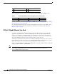
Removing and Installing GBICs Figure 16 Removing and Replacing a GBIC 98896 3 1 Locking tab 2 Locking tab 3 Alignment groove Inserting a GBIC into the Gigabit Ethernet Interface To insert a GBIC into the Gigabit Ethernet interface, follow these steps: Step 1 Attach an ESD wrist or ankle strap and follow its directions for use. Step 2 Locate the alignment groove on the GBIC. (See the enlargement in Figure 16 on page 25.
Removing and Installing SFP Modules Step 4 Using moderate force, ensure that the GBIC is fully inserted into the 20-pin receptacle at the rear of the GBIC slot. The tabs on either side of the GBIC will snap into place when you have completely and properly inserted the GBIC. Step 5 Reattach the SC-type fiber-optic cable to the GBIC. Removing and Installing SFP Modules Before you remove or install an SFP module, read the installation information in this section and the “Laser Safety” section on page 82.
Removing and Installing SFP Modules Removing a Bale Clasp SFP Module To remove this type of SFP module, follow these steps: Step 1 Attach an ESD-preventive wrist or ankle strap and follow its instructions for use. Step 2 Disconnect and remove all interface cables from the ports; note the current connections of the cables to the ports on the line card. Step 3 Open the bale clasp on the SFP module with your index finger in a downward direction, as shown in Figure 18.
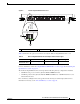
Removing and Installing SFP Modules Figure 18 Removing a Bale Clasp SFP Module ACTIVE CARRIER RX PACKET 2 3 ACTIVE W P RA CARRIER U THR RX PACKET S PAS S PAS THR U WR AP 4OC 48/S RP-S FP ACTIVE CARRIER RX PACKET 2 3 WR AP ACTIVE U CARRIER THR RX PACKET S PAS S PAS THR U WR AP 4OC 48/S RP-S 84508 FP Step 5 Place the removed SFP module on an antistatic mat, or immediately place it in a static shielding bag if you plan to return it to the factory.
Removing and Installing SFP Modules Step 6 Protect your line card by inserting clean SFP module cage covers into the optical module cage when there is no SFP module installed. Installing a Bale Clasp SFP Module To install this type of SFP module, follow these steps: Step 1 Attach an ESD-preventive wrist or ankle strap and follow its instructions for use. Step 2 Close the bale clasp before inserting the SFP module. Step 3 Line up the SFP module with the port and slide it into the port.
Removing and Installing SFP Modules Mylar Tab SFP Module 63065 Figure 20 Removing a Mylar Tab SFP Module To remove this type of SFP module, follow these steps: Step 1 Attach an ESD-preventive wrist or ankle strap and follow its instructions for use. Step 2 Disconnect and remove all interface cables from the ports; note the current connections of the cables to the ports on the line card.
Removing and Installing SFP Modules Step 5 Caution Protect your line card by inserting clean SFP module cage covers into the optical module cage when there is no SFP module installed. When pulling the tab to remove the SFP module, be sure to pull in a straight outward motion so you remove the SFP module from the port in a parallel direction. Do not twist or pull the tab, because you might disconnect it from the SFP module.
Removing and Installing SFP Modules Actuator Button SFP Module The actuator button SFP module includes a button that you push in order to remove the SFP module from a port. (See Figure 23.) Actuator Button SFP Module 63066 Figure 23 Removing an Actuator Button SFP Module To remove this type of SFP module, follow these steps: Step 1 Attach an ESD-preventive wrist or ankle strap and follow its instructions for use.
Removing and Installing SFP Modules Figure 24 Removing an Actuator Button SFP Module from a Port ACTIVE CARRIER RX PACKET 2 3 ACTIVE W P RA CARRIER U THR RX PACKET S PAS S PAS THR U WR AP 4OC 48/S RP-S FP ACTIVE CARRIER RX PACKET 2 3 WR AP ACTIVE U CARRIER THR RX PACKET S PAS S PAS THR U WR AP 4OC 48/S RP-S 84506 FP Step 4 Grasp the actuator button between your thumb and index finger and carefully pull the SFP module from the port.
Removing and Installing SFP Modules Step 6 Protect your line card by inserting clean SFP module cage covers into the optical module cage when there is no SFP module installed. Installing an Actuator Button SFP Module To install this type of SFP module, follow these steps: Step 1 Attach an ESD-preventive wrist or ankle strap and follow its instructions for use. Step 2 Line up the SFP module with the port and slide it in until the actuator button clicks into place. (See Figure 25.
Removing and Installing SFP Modules Slide Tab SFP Module 84651 Figure 26 Removing a Slide Tab SFP Module To remove this type of SFP module, follow these steps: Step 1 Attach an ESD-preventive wrist or ankle strap and follow its instructions for use. Step 2 Disconnect and remove all interface cables from the ports; note the current connections of the cables to the ports on the line card. Step 3 Grasp the SFP module between your thumb and index finger.
Removing and Installing SFP Modules Figure 28 Removing a Slide Tab SFP Module ACTIVE CARRIER RX PACKET 3 U S PAS THR AP WR 4OC 48/S RP-S 84650 FP Step 6 Place the removed SFP module on an antistatic mat, or immediately place it in a static shielding bag if you plan to return it to the factory. Step 7 Protect your line card by inserting clean SFP module cage covers into the optical module cage when there is no SFP module installed.
Line Card Cable-Management Bracket Figure 29 Installing a Slide Tab SFP Module RX PACKET ACTIVE CARRIER 2 3 RX PACKET W P RA ACTIVE THR CARRIER U S PAS S PAS THR U WR AP 4OC 48/S RP-S 84649 FP Note Verify that the SFP modules are completely seated and secured in their assigned receptacles on the line card by firmly pushing on each SFP module.
Line Card Cable-Management Bracket The cable-management system consists of two separate components: 1. A cable-management tray that is mounted on the chassis. Refer to the appropriate Cisco XR 12000 Series Router installation and configuration guide for more information on the cable-management tray. 2. A cable-management bracket that attaches to a line card. This section describes the line card cable-management bracket.
Note When shipped with spare line card orders, the cable-management bracket is not attached to the line card. You must attach the cable-management bracket to the line card before you insert the line card into the router. Caution Do not use the cable-management bracket as a handle to pull out or push in the line card. The cable-management bracket is designed to hold the interface cables and may break if you use the bracket to push, pull, or carry the line card after it is removed from the router.
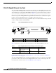
Figure 32 Multiport Line Card Cable-Management Installation and Removal (4-Port OC-48c/STM-16c DPT Line Card Shown) a b 1 CONNECTOR CLEAN WITH ALCOHOL WIPES BEFORE CONNECTING CONNECTOR CLEAN WITH ALCOHOL WIPES BEFORE CONNECTING CARRIER CARRIER RX PACKET RX PACKET 2 PA SS TH R WR U AP PA SS TH R WR U AP PRODUCTO LASER DE CLASSE 1 CLASS 1 LASER PRODUCT LASERPRODUKT DER KLASSE 1 PRODUIT LASER DE CLASSE 1 PRODUCTO LASER DE CLASSE 1 3 CLASS 1 LASER PRODUCT LASERPRODUKT DER KLASSE 1 PRODUIT
Figure 33 Single-Port Line Card Cable-Management Bracket Installation and Removal (1-Port OC-192c/STM-64c DPT Line Card Shown) 1 4 2 3 TXTX 80300 RXRX 1 Chassis cable-management tray 3 Interface cable 2 Cable clip 4 Line card cable-management bracket Installing a Line Card Cable-Management Bracket To install a line card cable-management bracket, follow these steps: Step 1 Attach an ESD-preventive wrist or ankle strap and follow its instructions for use.
Cabling and Specifications Step 2 Step 3 Attach the line card cable-management bracket to the line card as follows: a. Position the cable-management bracket over the front of the line card faceplate. b. Insert and tighten the captive screw(s) to secure the bracket to the line card. c. Starting with the bottom port on the line card, connect each interface cable to the intended port. For multiport line card cable-management brackets, carefully wrap the cables with the supplied Velcro strap.
Cabling and Specifications • Note 100BASE-TX and 100BASE-FX are commonly called 100BASE-X rather than 100BASE-T. • Note 100BASE-FX—100BASE-T, half- and full-duplex over fiber-optic cable. 100BASE-T4—100BASE-T, half- and full-duplex over Category 3, 4, or 5 UTP or shielded twisted-pair (STP) cabling with four pairs, also called 4T+. Two-pair UTP over Category 3 cable is called T2. The 8-Port Fast Ethernet line card supports 100BASE-TX and 100BASE-FX. 100BASE-T4 is not supported.
Cabling and Specifications Gigabit Ethernet Interface This section describes the Gigabit Ethernet interface: • GBIC Laser Optical Transceiver Modules, page 44 • Gigabit Ethernet SFP Modules, page 48 • 10-Gigabit Ethernet, page 50 GBIC Laser Optical Transceiver Modules The Gigabit Interface Converters (GBICs) are field-replaceable modules that plug into receptacles on the line card and provide the Gigabit Ethernet optical interface.
Cabling and Specifications Table 10 GBIC Module/ Connector WS-G5487= SC connector Ethernet GBIC Laser Optic Parameters (continued) Type Wavelength Fiber Type Distance1 Extended distance (single-mode) 1550 nm 10/9 micron SMF 8 micron SMF2 SMF 10/9 micron 43.5 miles (70 km) 62 miles (100 km) CWDM-GBIC-x Longwave (single-mode) xxx=3 1470-1610 nm4 62 miles (100 km) 1.
Cabling and Specifications 2. dBm = decibels referenced to 1 milliwatt. 3. Dispersion-shifted single-mode fiber-optic cable required for 100-km distance. 4. This distance represents best case conditions, depending on fiber quality, dispersion, and losses due to connectors, nodes, or splices.
Cabling and Specifications Table 12 Gigabit Ethernet CWDM GBIC Laser Optic Parameters (continued) GBIC Product Number CWDM GBIC Wavelength Color Identifier CWDM-GBIC-1550= CWDM-GBIC-1570= CWDM-GBIC-1590= CWDM-GBIC-1610= Longwave 1550 nm laser single-mode Longwave 1570 nm laser single-mode Longwave 1590 nm laser single-mode Longwave 1610 nm laser single-mode Yellow Orange Red Brown General CWDM GBIC Installation and Usage Guidelines The Cisco CWDM GBIC solution has two main components: the Cisco CWD
Cabling and Specifications • Always connect from transmit (TX) to receive (RX) when connecting GBICs to other equipment: – Connect GBIC TX to equipment RX – Connect GBIC RX to equipment TX • Optical transceivers—such as the Cisco CWDM GBICs—have a maximum optical receive power, above which damage might occur to the receive diode. The incoming power level might be too high if the fiber lacks sufficient attenuation, which might occur in a short run of fiber (less than approximately 25 km).
Cabling and Specifications The following SFP module options are available for a Gigabit Ethernet line card: • GLC-SX-MM—Short wavelength SFP module (850 nm nominal), for use in 1000BASE-SX links. • GLC-LH-SM—Long-haul or long-wavelength SFP module (1310 nm nominal), for use in 1000BASE-LX links. • GLC-LX-SM—Single-mode, long-reach • GLC-ZX-SM=—Single-mode, extended-reach (supported by 4-Port Gigabit Ethernet ISE line card only) The SFP modules have LC connectors.
Cabling and Specifications Note Use only the SFP modules supplied by Cisco with your Gigabit Ethernet line card. Each SFP module contains an internal serial EEPROM that is security-programmed by the SFP manufacturer with information that provides a way for Cisco (through the Cisco IOS software) to identify and validate the SFP module as a module type that was tested and qualified by Cisco to operate properly with Cisco Gigabit Ethernet line cards.
Cabling and Specifications Note • Single-mode—Generally yellow in color. • Multimode—Generally gray or orange in color. Multimode cables are multifiber cables that carry 12 channels of fiber data. For network applications using CWDM GBICs in Ethernet line cards, the CWDM GBICs use SMF patch cords only. Verify that all your patch cords are yellow (SMF), rather than orange (MMF).
Cabling and Specifications Figure 38 Simplex LC Cable Connector 75894 2 1 1 2 LC connector Duplex LC Cable Connector 30929 Figure 39 Spring-action disconnect latch TX RX Note Connectors on the fiber-optic cables must be free of dust, oil, or other contaminants. Before connecting the cable to the line card, carefully clean the fiber-optic connectors using an alcohol wipe or other suitable cleanser. Refer to the “Cleaning Fiber-Optic Connectors” section on page 56 for more information.
Cabling and Specifications Removing Fiber-Optic Interface Cables To remove line card interface cables, refer to Figure 40 (showing one possible arrangement) and follow these steps: Step 1 Attach an ESD-preventive wrist or ankle strap to your wrist and follow its instructions for use. Step 2 Press on the spring-action disconnect latch to disconnect the interface cable connectors from the line card interface ports.
Cabling and Specifications Figure 40 Disconnecting Line Card Interface Cables a b CONNECTOR CARRIER 0 ACTIVE 0 ACTIVE CLEAN WITH ALCOHOL WIPES BEFORE CONNECTING CONNECTOR CLEAN WITH ALCOHOL WIPES BEFORE CONNECTING 1 CARRIER RX PACKET RX PACKET PA SS TH R WR U AP PA SS TH R WR U AP PRODUCTO LASER DE CLASSE 1 CLASS 1 LASER PRODUCT LASERPRODUKT DER KLASSE 1 PRODUIT LASER DE CLASSE 1 PRODUCTO LASER DE CLASSE 1 CLASS 1 LASER PRODUCT LASERPRODUKT DER KLASSE 1 PRODUIT LASER DE CLASSE 1 CAR
Cabling and Specifications Warning Class 1 laser product. Warning Class 1 LED product (multimode). Note Connectors on the fiber-optic cables must be free of dust, oil, or other contaminants. Before connecting the cable to the line card, carefully clean the fiber-optic connectors using an alcohol wipe or other suitable cleanser. Refer to the “Cleaning Fiber-Optic Connectors” section on page 56 for more information.
Cabling and Specifications 1 TX connector 3 Simplex cables 2 RX connector 4 Duplex cable Figure 42 Attaching Simplex or Duplex Fiber Cables (Line Card Port or GBIC) GBIC with simplex or duplex SC connectors Duplex Simplex TX Note Duplex 22553 FAST ETHERNET Simplex 17464 RX TX RX The fiber-optic connectors must be free of dust, oil, or other contaminants. Carefully clean the fiberoptic connectors using an alcohol wipe or other suitable cleanser.
Cabling and Specifications The connection quality depends on two factors: the type of connector and the proper cleaning and connection techniques. Dirty fiber connectors are a common source of light loss. Keep the connectors clean at all times, and keep the dust plugs or covers installed when the connectors are not in use.
Verifying and Troubleshooting the Installation Removing RJ-45 Cables To remove line card cables, follow these steps (refer to Figure 44 on page 58): Step 1 Attach an ESD-preventive wrist or ankle strap to your wrist and follow its instructions for use. Step 2 Disconnect the interface cable connectors from the line card interface ports. You do not have to remove the interface cables from the line card cable-management bracket.
Verifying and Troubleshooting the Installation • Troubleshooting the Installation, page 64 Initial Boot Process Note Many new line cards are designated as administratively down by default. Status LEDs are off until you configure the interfaces and use the no shutdown command. During a typical line card boot process, the following events occur: 1. The line card maintenance bus (MBus) module receives power and begins executing the MBus software. 2.
Verifying and Troubleshooting the Installation Table 17 Status LED Descriptions LED Color/Activity Description LINK Green • A signal is detected. • There is RX synchronization. • The GBIC or SFP module is inserted and has no fault conditions. • The line card is connected to another functioning Gigabit Ethernet interface and has received comma-detect characters. • Loss of signal (LOS). Occurs when the signal is lost at the optical input.
Verifying and Troubleshooting the Installation Table 18 Alphanumeric LED Messages During a Typical Initialization Sequence LED Display1 Meaning Source MROM nnnn MBus microcode execute; nnnn is the microcode version number. MBus controller LMEM TEST Low memory on the line card is being tested. Line card ROM monitor LROM RUN Low memory test has been completed. Line card ROM monitor BSS INIT Main memory is being initialized.
Verifying and Troubleshooting the Installation Table 18 Alphanumeric LED Messages During a Typical Initialization Sequence (continued) LED Display1 Meaning Source IOS VGET2 Line card is obtaining the Cisco IOS version. RP IOS software IOS RUN Line card is enabled and ready for use. RP IOS software IOS STRT Cisco IOS software is being launched. RP IOS software IOS TRAN Cisco IOS software is transitioning to active. RP IOS software IOS UP Cisco IOS software is running. RP IOS software 1.
Verifying and Troubleshooting the Installation Table 19 Other Alphanumeric LED Messages (continued) LED Display Meaning Source CLOK DONE Slot clock configuration done. RP FABL LOAD Loading fabric downloader2 complete. RP IOS LOAD Downloading of Cisco IOS software is complete. RP BMA ERR Cisco IOS software BMA error. RP FIA ERR Cisco IOS fabric interface ASIC configuration error. RP CARV ERR Buffer carving failure. RP DUMP REQ Line card requesting a core dump.
Verifying and Troubleshooting the Installation 1. This LED sequence only appears in Cisco IOS release 12.0(24)S or later. 2. The fabric downloader loads the Cisco IOS software image onto the line card. Troubleshooting the Installation Note Many new line cards are designated as administratively down by default. Status LEDs are off until you configure the interfaces and use the no shutdown command.
Line Card Memory Note If you perform online insertion or removal of the GBIC or SFP without shutting down the interface, a warning message is displayed on the console device. Line Card Memory This section contains information about the following: • Line Card Memory Locations, page 65 • Removing and Installing Line Card Memory, page 69 You can replace the route memory on Ethernet line cards. Route memory modules are installed into 144-pin small-outline DIMM (SODIMM) sockets.
Line Card Memory Engine 2 Line Card Memory Locations Figure 45 shows the DIMM socket locations on an Engine 2 line card.
Line Card Memory Figure 46 ISE Line Card Memory Locations 4 3 84998 3 TX AN 1 TX TX ACTIV E CARR IER PKT RX WR AP THRU RX B PASS RX PKT 1 THRU A ACTIV E CARR IER RX WR AP CLAS LASE S 1 LA PRODRPRODUSER PR UIT LA KT DE ODUC SER R KLAS T PROD DE CL SE UCTO ASSE 1 LASE 1 R DE CLAS SE 1 PASS ACTIV E CARR IER RX 2 THRU WR AP PKT RX B PASS RX TX THRU PKT 0 WR AP ACTIV E CARR IER RX A PASS CLE WIT CO H WIP ALC NN ES OHO EC CON BEF L TO NEC ORE R TIN G 4O C1 2X /SR
Line Card Memory Engine 4 Line Card Memory Locations Figure 47 shows the DIMM socket locations on an Engine 4 line card. These line cards are equipped with five DIMM sockets: • One route memory small-outline DIMM (SODIMM) socket • Two pairs of packet memory DIMM sockets (not user serviceable) The route memory module is installed to a 144-pin SODIMM socket. Route memory runs the Cisco IOS software image and stores the updated network routing tables downloaded from the route processor.
Line Card Memory Table 21 Route Memory Configurations for Ethernet Line Cards (continued) Total Route Memory Cisco Product Number DIMM Module Route Memory DIMM Sockets 256 MB 256 MB 2 128-MB DIMMs 1 256-MB SODIMM DIMM0 and DIMM1 Varies MEM-GRP/LC-256= MEM-LC4-256=2 1. This option adds a second 64-MB DIMM for a total of 128 MB for line cards that are equipped with 64 MB. 2. This option is only compatible with the 4-Port Ethernet line cards and is for replacement only.
Line Card Memory – Size of the DIMMs in the transmit buffer need not match the size of the SDRAM DIMMs in the receive buffer. – DIMMs must be 3.3V devices.
Line Card Memory • For a socket with dual release levers (see Figure 48), pull down both levers at the same time to eject the DIMM. or • For a socket with a single release lever (see Figure 49), pull the lever to eject the DIMM. Caution Handle the edges of the DIMM only. Do not touch the integrated circuit devices on the DIMM, the metal traces, or fingers, along the edge of the DIMM, or the pins in the DIMM socket.
Line Card Memory Handling a DIMM H6507 Figure 50 Key Caution When inserting DIMMs into a socket, apply firm, but not excessive, pressure. If you damage a DIMM socket, you must return the line card for repair. Step 6 Gently insert the DIMM into the socket and push until the DIMM snaps into place and the release lever is flush against the side of the socket. Step 7 Verify that the release lever is flush against the side of the socket. If it is not, the DIMM might not be seated properly.
Line Card Memory Caution If the retaining clip is bent or damaged, do not attempt to fix or reuse it. This can cause serious damage to the line card. Each SODIMM replacement ships with a spare retaining clip, in case there is any damage to the existing clip. Remove Retaining Clip from Memory Module Socket 75779 Figure 51 Step 5 Remove the SODIMM by gently moving the plastic latches in an outward direction, parallel to and away from the memory module, until it releases and rotates to a 45-degree angle.
Line Card Memory Moving the Plastic Latch Away from the SODIMM 75799 Figure 52 Step 6 As the SODIMM is released, it positions itself at a 45-degree angle. Gently pull the SODIMM module out of the socket. Continue to keep the module at a 45-degree angle until it is completely removed from the socket guides. (See Figure 53b.) Figure 53 Removing a 144-pin SODIMM Module a b 75780 45º Step 7 Immediately place the SODIMM in an antistatic bag to protect it from ESD damage.
Line Card Memory Step 3 If there is a retaining clip, check to make sure that it has not been damaged or bent. (See Figure 54.) Note Some line cards do not require a retaining clip. SODIMM Socket Retaining Clip 75757 Figure 54 Caution If the retaining clip is damaged, do not use it. This can damage the SODIMM socket. Step 4 Locate the route memory socket on the line card. Step 5 Remove the new SODIMM from its protective antistatic bag. Caution Step 6 Grasp the edges of the SODIMM only.
Line Card Memory SODIMM with Key in Face-up Position 75759 Figure 55 Step 7 Note Step 8 The SODIMM must be lined up at a 45-degree angle. (See Figure 56a.) When the key is in the face-up position, the metal traces on the left side of the key measure 0.9 inch (23.20 mm). The metal traces on the right side of the key measure 1.29 inches (32.80 mm). The SODIMM can not be inserted until the keys are lined up properly.
Line Card Memory Caution Excessive pressure can damage a SODIMM socket. Step 10 Verify that the release levers are flush against the side of the socket. If they are not, the SODIMM might not be seated properly. Step 11 If the module appears misaligned, carefully remove it and reseat it, ensuring that the release lever is flush against the side of the SODIMM socket. Step 12 If there is a retaining clip, insert it by sliding the clip between the metal strain relief and the plastic latch.
Line Card Memory Retaining Clip Completely Installed into Module Latch 75781 Figure 58 Checking the Installation of Line Card Memory After you install line card memory and reinstall the line card in the router, the router reinitializes the line card and detects the memory change as part of the reinitialization cycle. The time required for the router to initialize can vary with different router configurations and memory configurations.
Regulatory, Compliance, and Safety Information If the router fails to restart properly after several attempts and you are unable to resolve the problem, access Cisco.com or contact your Cisco service representative for assistance. Before calling, however, make note of any console error messages, unusual LED states, or other router indications or behaviors that might help to resolve the problem.
Regulatory, Compliance, and Safety Information Modifying the equipment without Cisco’s authorization may result in the equipment no longer complying with FCC requirements for Class A digital devices. In that event, your right to use the equipment may be limited by FCC regulation and you may be required to correct any interference to radio or television communication at your own expense. You can determine whether your equipment is causing interference by turning it off.
Regulatory, Compliance, and Safety Information Class A Notice for Hungary Warning This equipment is a class A product and should be used and installed properly according to the Hungarian EMC Class A requirements (MSZEN55022). Class A equipment is designed for typical commercial establishments for which special conditions of installation and protection distance are used.
Regulatory, Compliance, and Safety Information VCCI Class A Notice for Japan Warning This is a Class A product based on the standard of the Voluntary Control Council for Interference by Information Technology Equipment (VCCI). If this equipment is used in a domestic environment, radio disturbance may arise. When such trouble occurs, the user may be required to take corrective actions.
Obtaining Documentation and Submitting a Service Request Class 1 Laser Product Warning (Single-mode) Warning Class 1 laser product. Class 1 LED Product Warning (Multimode) Warning Class 1 LED product. General Laser Warning Warning Invisible laser radiation can be emitted from the aperture of the port when no cable is connected. Avoid exposure to laser radiation and do not stare into open apertures.
Obtaining Documentation and Submitting a Service Request Cisco XR 12000 Series Router Ethernet Line Card Installation 84 OL-7861-01