Cisco 170 Series Hardware Installation Guide For Cisco C170 Email Security Appliance, Cisco M170 Content Security Management Appliance, and Cisco S170 Web Security Appliance Americas Headquarters Cisco Systems, Inc. 170 West Tasman Drive San Jose, CA 95134-1706 USA http://www.cisco.
THE SPECIFICATIONS AND INFORMATION REGARDING THE PRODUCTS IN THIS MANUAL ARE SUBJECT TO CHANGE WITHOUT NOTICE. ALL STATEMENTS, INFORMATION, AND RECOMMENDATIONS IN THIS MANUAL ARE BELIEVED TO BE ACCURATE BUT ARE PRESENTED WITHOUT WARRANTY OF ANY KIND, EXPRESS OR IMPLIED. USERS MUST TAKE FULL RESPONSIBILITY FOR THEIR APPLICATION OF ANY PRODUCTS.
CONTENTS Preface vii Contents vii Document Objectives Audience vii vii Document Organization viii Document Conventions viii Installation Warnings ix Where to Find Safety and Warning Information Related Documentation xiii xiii Obtaining Documentation and Submitting a Service Request CHAPTER 1 Cisco 170 Series Appliance 1-1 Cisco 170 Series Overview 1-1 Cisco C170 Email Security Appliance 1-2 Cisco M170 Content Security Management Appliance Cisco S170 Web Security Appliance 1-2 Cisco 170
Contents Preventive Site Configuration Power Supply Considerations Configuring Equipment Racks CHAPTER 2-4 2-5 2-7 Installing and Connecting the Cisco 170 Series Appliance 3 3--1 Installing the Cisco 170 Series Appliance with Slide Rails 3--1 Verifying the Box Contents 3--1 Disassembling the Slide Rail 3-0 Attaching Inner Rails to the Appliance 3-1 Verifying the Rack Type 3-2 Securing Round Hole Racks 3-3 Securing Threaded Hole Racks 3-3 Attaching the Outer Slide Rail to Round and Square Hole Racks A
Preface Contents This preface includes the following sections: • Document Objectives, page vii • Audience, page vii • Document Organization, page viii • Document Conventions, page viii • Installation Warnings, page ix • Where to Find Safety and Warning Information, page xiii • Related Documentation, page xiii • Obtaining Documentation and Submitting a Service Request, page xiii Document Objectives This guide describes how to install and maintain the Cisco 170 series appliance.
Document Organization This guide includes the following sections: Section Title Description 1 “Cisco 170 Series Appliance” Describes the Cisco 170 series appliance and its specifications. 2 “Preparing for Installation” Describes steps to follow before installing the Cisco 170 series appliance. 3 “Installing and Connecting the Cisco 170 Series Appliance” Describes how to install the Cisco 170 series appliance in a rack and provides information about how to connect interface cables.
Installation Warnings Before installing the appliance, be sure to read the Safety and Compliance Guide for the Cisco Content Security Appliances document at: http://www.cisco.com/en/US/docs/security/esa/hw/SafetyAndComplianceGuide.pdf. This document contains important safety information.
Wrist Strap Warning Warning During this procedure, wear grounding wrist straps to avoid ESD damage to the card. Do not directly touch the backplane with your hand or any metal tool, or you could shock yourself. Statement 94 Work During Lightning Activity Warning Warning Do not work on the system or connect or disconnect cables during periods of lightning activity.
Blank Faceplates and Cover Panels Warning Warning Blank faceplates and cover panels serve three important functions: they prevent exposure to hazardous voltages and currents inside the chassis; they contain electromagnetic interference (EMI) that might disrupt other equipment; and they direct the flow of cooling air through the chassis. Do not operate the system unless all cards, faceplates, front covers, and rear covers are in place.
Grounded Equipment Warning Warning This equipment is intended to be grounded. Ensure that the host is connected to earth ground during normal use. Statement 39 Safety Cover Requirement Warning The safety cover is an integral part of the product. Do not operate the unit without the safety cover installed. Operating the unit without the cover in place will invalidate the safety approvals and pose a risk of fire and electrical hazards.
Where to Find Safety and Warning Information For safety and warning information, see the Safety and Compliance Guide for the Cisco Content Security Appliances document at the following URL: http://www.cisco.com/en/US/docs/security/esa/hw/SafetyAndComplianceGuide.pdf This document describes the international agency compliance and safety information for the Cisco 170 series. It also includes translations of the safety warnings used in this guide.
Cisco 170 Series Hardware Installation Guide xiv OL-28365-01
CH A P T E R 1 Cisco 170 Series Appliance We recommend that you read the entire guide before beginning any of the procedures contained herein. Warning Only trained and qualified personnel should install, replace, or service this equipment. Statement 49 Caution Read the safety warnings in the Safety and Compliance Guide for the Cisco Content Security Appliances and follow proper safety procedures when performing any tasks in this document. See: http://www.cisco.
Chapter Cisco C170 Email Security Appliance Cisco C170 Email Security Appliance (Cisco C170) automatically stops spam, viruses, and other anomalies. It prevents and responds to multilevel threats and includes capabilities such as: spam and virus defense, policy enforcement, email authentication, and centralized and built-in GUI management tools. For information on Cisco C170, see: http://www.cisco.com/en/US/products/ps10154/tsd_products_support_series_home.
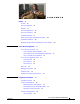
Chapter Figure 1-3 shows the Cisco S170 front panel view. Figure 1-3 Cisco S170 Web Security Appliance Cisco 170 Series Appliance Panels This section describes the front and rear Cisco 170 series appliance panels. It includes the following topics: • Front Panel LEDs, page 1-3 • Rear Panel LEDs, page 1-5 • Rear Panel Ports, page 1-6 Front Panel LEDs This section describes the front panel LEDs for the Cisco 170 series appliance.
Chapter 1 2 LED Description Power button A hard switch that turns the system on and off. Once depressed, the button stays in the “on” position: Alarm • On—The power symbol on the button illuminates. • Off—The power symbol on the button is dark. Indicates system operating status: • Off—Normal operating system function. • Solid amber—Critical Alarm indicating one or more of the following: – A major failure of a hardware or software component. – An over-temperature condition.
Chapter Rear Panel LEDs This section describes the rear panel LEDs for the Cisco 170 series appliance. Figure 1-5 shows the rear panel LEDs that are available for the Cisco C170, Cisco M170 and Cisco S170 models (graphic shows the Cisco S170 rear panel). Figure 1-5 Rear Panel LEDs for Cisco C170, Cisco M170 and Cisco S170 1 4 3 303135 2 1 2 LED Description Power Indicates power supply status: Alarm • Off—Power supply off. • Solid green—Power supply on.
Chapter 3 4 LED Description HD0 Indicates Hard Disk Drive 0 status: HD1 • Flashing green—Proportioned to read/write activity. • Solid amber—Hard disk drive failure. • Flashing amber—Hard disk drive being rebuilt. • Off—No hard disk drive present. Indicates Hard Disk Drive 1 status: • Flashing green—Proportioned to read/write activity. • Solid amber—Hard disk drive failure. • Flashing amber—Hard disk drive being rebuilt. • Off—No hard disk drive present.
Chapter . 1 LED Description Management interface Indicates the Gigabit Ethernet interface that is restricted to management use only. Connect with an RJ-45 cable. See the “Management Interface” section on page 1-8. 2 Power supply Indicates the appliance power supply. 3 RJ-45 ports Indicates the Gigabit Ethernet customer data interfaces. The port numbers are (from left to right) P1, P2, T1 and T2. 4 USB Ports1 Indicates the two USB standard ports.
Chapter 2 RJ-45 ports Indicates the Gigabit Ethernet customer data interfaces. The port numbers are (from left to right) Data 1 and Data 2. 3 USB Ports1 Indicates the two USB standard ports. 4 Console port Indicates the console port that directly connects a computer to the Cisco 170 series appliance. 1. USB ports can be used in future software releases.
Chapter Hardware and Technical Specifications Table 1-1 contains hardware and technical specifications for the Cisco 170 series. Table 1-1 Hardware and Technical Specifications for Cisco C170, Cisco M170 and Cisco S170 Specifications Cisco C170 Cisco M170 Cisco S170 Form-factor 1 RU, 14-in 1 RU, 14-in 1 RU, 14-in Rack mountable Yes Slide rails (standard) Brackets (spares) Yes Slide rails (standard) Brackets (spares) Yes Slide rails (standard) Brackets (spares) Dimensions 1.67 x 16.9 x 15.
Chapter Table 1-1 Hardware and Technical Specifications for Cisco C170, Cisco M170 and Cisco S170 (Continued) Specifications Cisco C170 Cisco M170 Cisco S170 Command Line Interface SSH or Telnet (command based) SSH or Telnet (command based) SSH or Telnet (command based) Logging Syslog Squid, Apache, Syslog, W3C Squid, Apache, Syslog Centralized Reporting Supported Supported Supported File Transfer SCP, FTP SCP, FTP SCP, FTP Configuration Files XML-based XML-based XML-based Central
CH A P T E R 2 Preparing for Installation This chapter describes the steps to follow before installing the Cisco 170 series appliance or performing hardware maintenance.
Chapter • Cisco M170 Content Security Management Appliance Quick Start Guide: http://www.cisco.com/en/US/docs/security/security_management/sma/hw/quick_start/M170_QSG .pdf • Cisco S170 Web Security Appliance Quick Start Guide: http://www.cisco.com/en/US/docs/security/wsa/hw/S170_QSG.pdf Safety Recommendations Use the following guidelines and the information in the following sections to help ensure your safety and protect the Cisco 170 series appliance.
Chapter • If an electrical accident occurs, proceed as follows: – Use caution; do not become a victim yourself. – Disconnect power from the system. – If possible, send another person to get medical aid. Otherwise, assess the condition of the victim, and then call for help. – Determine whether or not the person needs rescue breathing or external cardiac compressions; then take appropriate action. • Use the Cisco 170 series appliance within its marked electrical ratings and product usage instructions.
Chapter General Site Requirements The topics in this section describe the requirements your site must meet for safe installation and operation of your Cisco 170 series system. Ensure that your site is properly prepared before beginning installation.
Chapter Power Supply Considerations The Cisco 170 series hardware operates on AC power and supports the ability to restore the previous power state of the system in the event that AC power is lost. Be aware of the following when interacting with system hardware: • The Cisco 170 series appliance requires 50 seconds from the time that AC power is applied before the power state can be updated and stored.
Chapter Table 2-1 AC-Input Power Cord Options (Continued) Part Number Length Plug Rating Italy CAB-ACI 72-0556 8.2 ft (2.5 m) 250 VAC, 10 A Singapore CAB-ACU 72-0557 8.2 ft (2.5 m) 250 VAC, 10 A Argentina CAB-ACR (37-0995-01) 8.2 ft (2.5 m) 250 VAC, 10 A Switzerland CAB-ACS (72-1483-01) 8.2 ft (2.5 m) 250 VAC, 10 A Japan CAB-JPN (72-1925-01) 8.2 ft (2.5 m) 250 VAC, 10 A India CAB-IND-10A 8.2 ft (2.
Chapter Configuring Equipment Racks The following tips help you plan an acceptable equipment rack configuration: • Enclosed racks must have adequate ventilation. Ensure that the rack is not overly congested because each appliance generates heat. An enclosed rack should have louvered sides and a fan to provide cooling air. • When mounting a appliance in an open rack, ensure that the rack frame does not block the intake or exhaust ports.
Chapter Cisco 170 Series Hardware Installation Guide 2-8 OL-28365-01
CH A P T E R 3 Installing and Connecting the Cisco 170 Series Appliance This chapter describes how to install the Cisco 170 series (Cisco 170 series) appliance using slide rails (standard configuration) or rack-mounting it (optional configuration) and provides information on how to connect the interface cables.
Chapter • A—Slide rails (x2) (preconfigured for square hole racks) • B— Phillips flat-head screws for Inner Slide (x2) For round hole racks, you also need the following: • • C—Round hole inserts (x4) Phillips screwdriver For threaded hole racks, you also need the following: • D—Threaded hole brackets (x2) • E—Threaded hole standoffs (x2) • F—Phillips pan-head screws for threaded hole racks (x8) • Flat-head screwdriver Figure 3-1 Appliance Box Contents A C D E F 300885 B Note By defa
Chapter Front Slide the plastic tab forward, and pull the inner slide rail to disconnect it from the outer slide rail. Step 3 Repeat the previous steps for the other slide rail. 330908 Step 2 Attaching Inner Rails to the Appliance Align one of the inner slide rail key holes over the appliance shoulder screw on one side. Slide the inner slide rail forward so that the shoulder screw is securely in place.
Chapter Use a Phillips screwdriver to secure the inner slide rail with one Phillips flat-head screw (See B in Figure 3-1). Step 3 Secure the other inner slide rail to the appliance by repeating the previous steps. 330904 330905 Step 2 Verifying the Rack Type Step 1 The slide rails are pre-assembled for square hole racks. Use the following steps for the different rack types: • For square hole racks, see the “Attaching the Outer Slide Rail to Round and Square Hole Racks” section on page 3-4.
Chapter Securing Round Hole Racks Using a Phillips head screwdriver, remove the square insert from the rear of the rail. Retain the two Phillips head screws. Step 2 Remove the square insert from the front of the rail. Retain the two Phillips head screws. Step 3 Align the round hole insert (see C in Figure 3-1) to the rear of the rail, and secure it with two of the saved screws.
330884 Chapter Remove the square hole insert from the front of the rail. Step 3 Align the threaded hole bracket (see D in Figure 3-1) to the front of the rail over the hooks. Secure it with the threaded hole standoff (see E in Figure 3-1) using a flat-head screwdriver. Step 4 No additional hardware is necessary for the rear adapter. Step 5 Repeat the previous steps page for the other slide rail. Step 6 Proceed to the “Attaching the Outer Slide Rail to Threaded Hole Racks” section on page 3-5.
Chapter Front of Rack Rear of Rack 330901 Rear of Bracket Secure the other outer slide rail to the rack by repeating the previous steps. Step 3 Proceed to the “Installing the Appliance” section on page 3-6. 330872 Step 2 Attaching the Outer Slide Rail to Threaded Hole Racks Align the slide rail to the front rack post. Secure it with two of the included Phillips pan-head screws (see F in Figure 3-1).
Chapter Align the slide rail to the rear rack post. Secure it with two of the included Phillips pan-head screws (see F in Figure 3-1). Step 3 Align the other slide rail to the rack by repeating the previous steps. Step 4 Proceed to the “Installing the Appliance” section on page 3-6. 330872 330875 Step 2 Installing the Appliance Align the inner slide rails to the outer slide rails. Install the inner slide rails into the outer slide rails until they lock into place.
Chapter Pull the side release tabs to unlock the inner slide rail and push the appliance assembly into the rack. 330898 Step 2 Securing the Appliance Secure the appliance to the rack with the front captive screws.
Chapter Rack Mounting the Cisco 170 Series Appliance If you have 2-post racks, you can order the rack mount spares to rack-mount the Cisco 170 series appliance as described in this section.
Chapter Figure 3-2 Step 2 Install a fixed rack-mount bracket to both sides of the appliance by aligning the screw holes on the appliance to the slots and holes on the bracket. The bracket will be set back from the front faceplate (bezel). Secure each bracket with three screws. See Figure 3-3.
Chapter Figure 3-4 Attaching the C170, M170, or S170 Appliance to the Rack 330840 HOT AISLE Rear I/O Cisco ASA Adapative Security5545 Appliance BOOT ACTIVE PS1 PS0 ALARM VPN HD1 HD0 1 AIR FLOW DIRECTION 0 COLD AISLE Front Bezel Connecting the Interface Cables and Verifying Connectivity This section describes how to connect the cables to the Console, Auxiliary, and Management ports. Warning Only trained and qualified personnel should install, replace, or service this equipment.
Chapter For more information, see Figure 1-7 on page 1-6 for an illustration of the port in the Cisco S170 model appliance. – Connect one RJ-45 connector to the management interface port. – Connect the other end of the Ethernet cable to the management port on your computer and make sure that your computer is configured to obtain an IP address using DHCP. b. Console port—for use with the CLI. – Connect the serial console cable.
Chapter Cisco 170 Series Hardware Installation Guide 3-12 OL-28365-01
CH A P T E R 4 Maintaining the Cisco 170 Series Appliance This chapter provides maintenance information about the Cisco 170 series appliance, including information on how to replace the pre-installed hard disk drives (HDDs). This chapter includes the following sections: • Fixed AC Power Supply, page 4-1 • Removing and Installing Hard Disk Drives, page 4-1 • Contacting Service and Support, page 4-3 Fixed AC Power Supply The Cisco 170 series appliance ships with one fixed power supply (AC) installed.
Chapter Maintenance Scenarios Note Make sure that you replace the Cisco 170 series HDDs with Cisco supplied HDDs that are specific to and preconfigured for the Cisco 170 series appliance. Please contact Cisco Technical Support for more information or in case of an Return Merchandise Authorization (RMA). See the “Contacting Service and Support” section on page 4-3.
Chapter Figure 4-2 shows the Cisco 170 series appliance with one HDD being inserted. Installing a HDD in the Cisco 170 Series Appliance 334565 Figure 4-2 Step 3 On the front panel of the Cisco 170 series appliance, make sure the HDD1 and HDD0 indicators are flashing green to indicate that the hard disk drives are now active.
Chapter Cisco 170 Series Hardware Installation Guide 4-4 OL-28365-01
A P P E N D I X A Identifying Cable Pinouts This appendix describes pinout information for the 10/100/1000BaseT ports and the RJ-45 to DB-9 ports, and the RJ-45 cables for the console port. This chapter includes the following sections: • 10/100/1000BaseT Connectors, page A-1 • Console Port (RJ-45), page A-2 • RJ-45 to DB-9, page A-3 10/100/1000BaseT Connectors The Cisco 170 series appliance supports 10/100/1000BaseT ports.
Appendix Console Port (RJ-45) Cisco products use the following types of RJ-45 cables: Note • Straight-through • Crossover Cisco does not provide these cables, yet they are widely available from other sources. Figure A-2 shows the RJ 45 cable. RJ-45 Cable H2936 Figure A-2 87654321 RJ-45 connector To identify the RJ-45 cable type, hold the two ends of the cable next to each other so that you can see the colored wires inside the ends, as shown in Figure A-3.
Appendix Table A-1 RJ-45 Rolled (Console) Cable Pinouts (Continued) Signal Pin Pin Pin - 4 5 - - 5 4 - - 6 3 - - 7 2 - - 8 1 - RJ-45 to DB-9 Table A-2 lists the cable pinouts for RJ-45 to DB-9.
Appendix Cisco 170 Series Hardware Installation Guide A-4 OL-28365-01