Cisco Communication Media Module for Catalyst 6500 Series Switch and Cisco 7600 Series Router Installation and Verification Note Product Number: WS-SVC-CMM Last Updated: March 23, 2009 This publication contains the procedures for installing and configuring the Catalyst 6500 series switch and Cisco 7600 series router Communication Media Module (CMM).
Contents Contents This publication contains these sections: • Front Panel Descriptions, page 2 • Requirements, page 6 • Safety Overview, page 7 • Required Tools, page 10 • Installing and Removing the Module, page 10 • Removing and Replacing Port Adapters, page 19 • Verifying the Installation, page 25 • RJ-45 Port Connector and Cabling Specifications, page 25 • RJ-21 Port Connector and Cabling Specifications, page 27 • Accessing the Port Adapter Ports, page 28 • Configuring the Port Ada
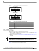
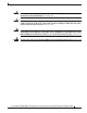
Front Panel Descriptions Note For information on the supervisor engine LEDs, see the Catalyst 6500 Series Switch Supervisor Engine Guide at this URL: http://www.cisco.com/en/US/docs/switches/lan/catalyst6500/hardware/Module_Installation/Sup_Eng_ Guide/supe_gd.html Figure 1 CMM Front Panel Features Interface Module slots WS-SVC-CMM-6E1 1 2 3 4 5 0 1 2 3 4 5 ST AT US RE ST AR AT U 0 Communication Media Module 6-Port E1 Interface Port Adapter. 6-Port E1 Interface Port Adapter.
Front Panel Descriptions Table 2 Rear Module STATUS LED Color Description Green Port adapter in slot 4 is up and operational. Red Port adapter in slot 4 is shut down. No light Slot 4 port adapter is not located by the system. 6-Port T1 and E1 Port Adapters The front panel features of the 6-port T1 and E1 port adapters are as follows: • Receive port LEDs—The LEDs on the front panel indicate the status of each T1 and E1 interface. Table 3 describes the receive port LED operation.
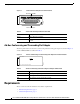
Front Panel Descriptions Figure 2 6-Port T1 and E1 Port Adapter Front Panel Features Receive port LEDs WS-SVC-CMM-6T1 1 2 3 4 5 68448 0 6-Port T1 Interface Port Adapter RJ-45 connectors Receive port LEDs WS-SVC-CMM-6E1 1 2 3 4 5 68449 0 6-Port E1 Interface Port Adapter RJ-45 connectors Table 3 6-Port T1 and E1 Port Adapters Receive Port LEDs Color Description Green T1/E1 interface is operational. Red T1/E1 receive alarm. Yellow T1/E1 remote alarm.
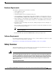
Requirements Figure 3 24-Port FXS Port Adapter Front Panel Features Receive port LEDs 98289 WS-SVC-CMM-24FXS FXS Interface Board Adapter RJ-21 connector Table 4 24-Port FXS Port Adapter Receive Port LEDs Color Description Green Port is off-hook or ringing. Off Port is not active (connected device on-hook) or is disabled through the CLI.
Safety Overview Hardware Requirements The hardware requirements for the modules are as follows: • Catalyst 6500 series switch. • Cisco 7600 series router. • 252.0 Watts (6.00 A @ 42 V) of available system power • A Supervisor Engine 2, Supervisor Engine 720, or Supervisor Engine 32—The supervisor engine can have an MSFC, MSFC2, or MSFC3, but the CMM does not require one for configuration or operation. • Supervisor Engine 32—The minimum version for the CMM is 12.
Safety Overview Warning Ultimate disposal of this product should be handled according to all national laws and regulations. Statement 1040 Warning Only trained and qualified personnel should be allowed to install, replace, or service this equipment. Statement 1030 Warning If the symbol of suitability with an overlaid cross appears above a port, you must not connect the port to a public network that follows the European Union standards.
Safety Overview Warning Never touch uninsulated telephone wires or terminals unless the telephone line has been disconnected at the network interface. Statement 1037 Warning Hazardous network voltages are present in WAN ports regardless of whether power to the unit is OFF or ON. To avoid electric shock, use caution when working near WAN ports. When detaching cables, detach the end away from the unit first.
Required Tools Required Tools Warning Only trained and qualified personnel should be allowed to install, replace, or service this equipment.
Installing and Removing the Module Step 3 Verify that there is enough clearance to accommodate any interface equipment that you will connect directly to the module ports. If possible, place modules between empty slots that contain only module filler plates. Step 4 Verify that the captive installation screws are tightened on all modules that are installed in the chassis. This action ensures that the EMI gaskets on all modules are fully compressed to maximize the opening space for the replacement module.
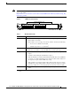
Installing and Removing the Module Figure 5 Positioning the Module in a Horizontal Slot Chassis Insert module between slot guides EMI gasket 3 4 5 6 4 5 6 WS-X6K-SUP2-2GE 1 ST AT US SY ST OL EM T E NS CO R M PW GM SE Switch 100% T Load CONSOLE PORT MODE RE PORT 1 PORT 2 CONSOLE SUPERVISOR2 PCMCIA EJECT 1% WS-X6K-SUP2-2GE 2 ST AT US SY ST OL EM T E NS CO R PW M GM SE Switch 100% T Load CONSOLE PORT MODE RE PORT 1 PORT 2 CONSOLE SUPERVISOR2 PCMCIA EJE
Installing and Removing the Module Figure 6 Clearing the EMI Gasket in a Horizontal Slot Chassis WS-X6K-SUP2-2GE T M LE G O US EM M T AT NS R ST SE ST SY CO PW RE 1 Switch 100% CONSOLE Load CONSOLE PORT MODE SUPERVISOR2 PORT 1 PCMCIA PORT 2 EJECT 1% WS-X6K-SUP2-2GE NK LI T M LE G O US EM M T AT NS R ST SE ST SY CO PW RE 2 Switch 100% CONSOLE SUPERVISOR2 CONSOLE PORT MODE NK LI Load PORT 1 PCMCIA PORT 2 EJECT 1% NK LI NK LI 3 Press down 4 FAN STATUS 5 Press down WS-X6224 S TU S
Installing and Removing the Module Figure 7 Ejector Lever Closure in a Horizontal Slot Chassis WS-X6K-SUP2-2GE T M LE G O US EM M T AT NS R ST SE ST SY CO PW RE 1 Switch 100% CONSOLE SUPERVISOR2 Load CONSOLE PORT MODE PORT 1 PCMCIA PORT 2 EJECT 1% WS-X6K-SUP2-2GE NK LI T M LE G O US EM M T AT NS R ST SE ST SY CO PW RE 2 Switch 100% CONSOLE SUPERVISOR2 PORT 1 PCMCIA NK LI Load CONSOLE PORT MODE PORT 2 EJECT 1% NK LI NK LI 3 4 FAN STATUS 5 WS-C6500-SFM S TU STA SWITCH FABRIC M
Installing and Removing the Module Figure 8 Positioning the Module in a Vertical Slot Chassis Ejector lever fully extended WS-C6500-SFM SWITCH FABRIC MDL FAN STATUS WS-X6K-SUP2-2GE STA TUS SYS MT OLE MG TEM NS R SET RE PW CO MT E M S OL T MG TU R NS SE STE RE PW CO SY STA WS-X6K-SUP2-2GE SUPERVISOR2 SUPERVISOR2 ST AT CONSOLE CONSOLE AC US CONSOLE PORT MODE PORT MODE WS-X6224 24 PORT 100FX CONSOLE TIV E ST AT US AC TIV E PCMCIA PCMCIA EJECT EJECT Switch Switch 1% 100% 1%
Installing and Removing the Module Figure 9 Clearing the EMI Gasket in a Vertical Slot Chassis Gap between the module EMI gasket and the module above it 1 mm WS-C6500-SFM SWITCH FABIRD MDL US AT ST E TIV AC FAN STATUS WS-X6K-SUP2-2GE STA TUS SYS AT US MT OLE MG TEM NS R SET RE PW CO ST MT E M S OL T MG TU R NS SE STE RE PW CO SY STA WS-X6K-SUP2-2GE SUPERVISOR2 SUPERVISOR2 WS-X6224 24 PORT 100FX AC E CONSOLE CONSOLE TIV PORT CONSOLE PORT MODE MODE CONSOLE Press left PCMCIA PCMCIA
Installing and Removing the Module Figure 10 Ejector Lever Closure in a Vertical Slot Chassis FAN STATUS ST WS-X6K-SUP2-2GE SUPERVISOR2 AT US SY ST CO EM NS O PW LE R M M RE G SE T S TU STA T M LE G O T M EM US R NS SE ST AT RE PW CO SY ST WS-X6K-SUP2-2GE SUPERVISOR2 WS-X6224 24 PORT 100FX T CONSOLE CONSOLE VE TI AC CONSOLE PORT MODE CONSOLE PORT MODE PCMCIA PCMCIA EJECT EJECT 100% Switch Switch 1% 1% 100% SE LE PORT 1 PORT 1 XT Load Load NE CT 63587 PORT 2 P
Installing and Removing the Module To remove a module from the chassis, perform these steps: Step 1 Disconnect any network interface cables that are attached to the module. Step 2 Verify that the captive installation screws on all of the modules in the chassis are tight. This step assures that the space that is created by the removed module is maintained.
Removing and Replacing Port Adapters Removing and Replacing Port Adapters Follow the procedures in this section to remove and replace the port adapters on the CMM: • Removing a Port Adapter from Module Slots 1 through 3, page 19 • Installing a Port Adapter in Module Slots 1 through 3, page 22 • Installing and Removing an Ad-Hoc Conferencing and Transcoding Port Adapter in Slot 4, page 23 Removing a Port Adapter from Module Slots 1 through 3 Note When you face the module front panel, slot 1 is on the
Removing and Replacing Port Adapters To install the module into the Catalyst 6500 series switch or the Cisco 7600 series router, see the “Installing the Module” section on page 10.
Removing and Replacing Port Adapters Figure 12 Module (Top View with Port Adapters Installed) Slot 4 standoffs (2) Slot 4 Phillips screws (2) Standoffs (6) 1 2 3 4 5 6 WS-X6600-6EI 1 2 3 4 5 6 S TA T U S WS-X6600-6TI R S EA TA R T U MD S L WS-X6600 AVVID Services Module Figure 13 6Port TI Intfc Mdl 6Port EI Intfc Mdl 68453 Phillips screws (6) Module (Top View with Port Adapters Removed) Slot 4 connectors (2) Slot 4 Phillips screw mounting posts (2) Slot 4 standoff mounting
Removing and Replacing Port Adapters Installing a Port Adapter in Module Slots 1 through 3 Note When you face the module front panel, slot 1 is on the left, slot 2 is in the middle, and slot 3 is on the right. Slot 4 is located internally. (See Figure 13.) To install a port adapter in module slots 1 through 3, perform these steps: Warning Hazardous voltage or energy is present on the backplane when the system is operating. Use caution when servicing.
Removing and Replacing Port Adapters Caution Using the screws or standoffs to seat the port adapter could warp the port adapter. Before you install and tighten the securing screws, ensure that the port adapter is fully seated by visually verifying that the bottom of the port adapter is in contact with the top of the mounting posts. Step 8 Install the two standoffs and two Phillips screws to secure the port adapter. (See Figure 12.
Removing and Replacing Port Adapters Step 4 In Figure 13, note the location of the two slot 4 standoff mounting posts. Remove the two mounting posts that secure the port adapter. Step 5 In Figure 13, note the location of the two slot 4 connectors. Carefully remove the port adapter, taking care when lifting up and disconnecting the port adapter from the connectors.
Verifying the Installation Caution Using the screws or standoffs to seat the port adapter could warp the port adapter. Before you install and tighten the securing screws, ensure that the port adapter is fully seated by visually verifying that the bottom of the port adapter is in contact with the top of the mounting posts. Step 6 Install the two standoffs and two Phillips screws to secure the port adapter. (See Figure 12.
RJ-45 Port Connector and Cabling Specifications Warning Hazardous network voltages are present in WAN ports regardless of whether power to the unit is OFF or ON. To avoid electric shock, use caution when working near WAN ports. When detaching cables, detach the end away from the unit first. Statement 1026 Warning To avoid electric shock, do not connect safety extra-low voltage (SELV) circuits to telephone-network voltage (TNV) circuits.
RJ-21 Port Connector and Cabling Specifications RJ-21 Port Connector and Cabling Specifications Warning Caution If the symbol of suitability with an overlaid cross appears above a port, you must not connect the port to a public network that follows the European Union standards. Connecting the port to this type of public network can cause severe personal injury or can damage the unit.
Accessing the Port Adapter Ports Table 7 RJ-21 Connector Pinouts Port Number Connector Pin Number Signal Port Number Connector Pin Number Signal 1 1 26 Ring Tip 13 13 38 Ring Tip 2 2 27 Ring Tip 14 14 39 Ring Tip 3 3 28 Ring Tip 15 15 40 Ring Tip 4 4 29 Ring Tip 16 16 41 Ring Tip 5 5 30 Ring Tip 17 17 42 Ring Tip 6 6 31 Ring Tip 18 18 43 Ring Tip 7 7 32 Ring Tip 19 19 44 Ring Tip 8 8 33 Ring Tip 20 20 45 Ring Tip 9 9 34 Ring Tip 21 21 46 Ring Tip
Configuring the Port Adapter Ports Configuring the Port Adapter Ports Configuring the module interfaces is similar to configuring the voice interfaces on other Cisco products. module interface configuration requirements are dependent on your AVVID network requirements. Note The module requires a static IP address. Obtaining an IP address through a DHCP server is not supported.
Disaster Recovery for Module Software Upgrades Disaster Recovery for Module Software Upgrades This section describes how to recover in the event that the CMM software image fails to load properly. If there is a corrupted image in the CMM bootflash, the CMM does not come online and stays at the ROMMON prompt. You will need to perform these steps to replace the corrupted image: Step 1 Copy a new image to the supervisor engine flash memory.
Disaster Recovery for Module Software Upgrades Disaster Recovery for Supervisor Engines Running Catalyst Operating System Software To perform disaster recovery on systems that use the Catalyst operating system software on the supervisor engine, perform these steps: Step 1 Before performing the disaster recovery, remove the port adapters from the CMM. See the “Removing and Replacing Port Adapters” section on page 19 for removal procedures.
Password Recovery Step 3 Under the CLI Config mode, enter the tftp-server [device]:[golden-image] alias [alias-name] command to translate the filename of the downloaded file. The [golden-image] is the file to be downloaded, and the [device] can be any flash file system on the supervisor engine. See Table 8 for configuring the appropriate [alias-name] corresponding to the supervisor engine type in use.
Regulatory Standards Compliance Regulatory Standards Compliance Catalyst 6500 series switches and modules comply with the regulatory standards that are listed in the Regulatory Compliance and Safety Information for the Catalyst 6500 Series Switches publication at this URL: http://www.cisco.com/en/US/docs/switches/lan/catalyst6500/hardware/RC/78_12928.
Obtaining Documentation, Obtaining Support, and Security Guidelines This document is to be used in conjunction with the documents listed in the “Related Documentation” section. Cisco and the Cisco logo are trademarks or registered trademarks of Cisco and/or its affiliates in the U.S. and other countries. To view a list of Cisco trademarks, go to this URL: www.cisco.com/go/trademarks. Third-party trademarks mentioned are the property of their respective owners.