CH A P T E R 7 Controlling Lightweight Access Points This chapter describes the Cisco lightweight access points and explains how to connect them to the controller and manage access point settings.
Chapter 7 Controlling Lightweight Access Points Access Point Communication Protocols Access Point Communication Protocols In controller software release 5.2 or later, Cisco lightweight access points use the IETF standard Control and Provisioning of Wireless Access Points protocol (CAPWAP) to communicate between the controller and other lightweight access points on the network. Controller software releases prior to 5.2 use the Lightweight Access Point Protocol (LWAPP) for these communications.
Chapter 7 Controlling Lightweight Access Points Access Point Communication Protocols with one discovery type (CAPWAP or LWAPP) exceeds the maximum discovery count and the access point does not receive a discovery response, the discovery type changes to the other type. For example, if the access point does not discover the controller in LWAPP, it starts the discovery process in CAPWAP.
Chapter 7 Controlling Lightweight Access Points Access Point Communication Protocols domain name. When an access point receives an IP address and DNS information from a DHCP server, it contacts the DNS to resolve CISCO-LWAPP-CONTROLLER.localdomain. When the DNS sends a list of controller IP addresses, the access point sends discovery requests to the controllers. Verifying that Access Points Join the Controller When replacing a controller, you need to make sure that access points join the new controller.
Chapter 7 Controlling Lightweight Access Points Configuring Global Credentials for Access Points Viewing CAPWAP MTU Information To view the maximum transmission unit (MTU) for the CAPWAP path on the controller, enter this command. The MTU specifies the maximum size of any packet (in bytes) in a transmission. show ap config general Cisco_AP Information similar to the following appears: Cisco AP Identifier.............................. 9 Cisco AP Name....................................
Chapter 7 Controlling Lightweight Access Points Configuring Global Credentials for Access Points Also in controller software release 5.0 or later, after an access point joins the controller, the access point enables console port security, and you are prompted for your username and password whenever you log into the access point’s console port. When you log in, you are in non-privileged mode, and you must enter the enable password in order to use the privileged mode.
Chapter 7 Controlling Lightweight Access Points Configuring Global Credentials for Access Points Step 2 In the Username field, enter the username that is to be inherited by all access points that join the controller. Step 3 In the Password field, enter the password that is to be inherited by all access points that join the controller. Step 4 In the Enable Password field, enter the enable password that is to be inherited by all access points that join the controller.
Chapter 7 Controlling Lightweight Access Points Configuring Global Credentials for Access Points Using the CLI to Configure Global Credentials for Access Points Using the controller CLI, follow these steps to configure global credentials for access points that join the controller.
Chapter 7 Controlling Lightweight Access Points Configuring Authentication for Access Points Information similar to the following appears: Cisco AP Identifier.............................. 0 Cisco AP Name.................................. HReap ... AP User Mode..................................... AUTOMATIC AP User Name..................................... globalap ... Note If this access point is configured for global credentials, the AP User Mode fields shows “Automatic.
Chapter 7 Controlling Lightweight Access Points Configuring Authentication for Access Points Note If you choose to follow this suggested flow and enable 802.1X authentication on the switch port after the access point has joined the controller and received the configured 802.1X credentials, you do not need to enter this command. Note This command is available only for access points that are running the 5.1 or 5.2 recovery image. c. Connect the access point to the switch port. 2. Install the 5.1 or 5.
Chapter 7 Controlling Lightweight Access Points Configuring Authentication for Access Points Step 4 In the Password and Confirm Password fields, enter the password that is to be inherited by all access points that join the controller. Note You must enter a strong password in these fields. Strong passwords have the following characteristics: - They are at least eight characters long. - They contain a combination of upper- and lowercase letters, numbers, and symbols.
Chapter 7 Controlling Lightweight Access Points Configuring Authentication for Access Points f. Click Apply to commit your changes. g. Click Save Configuration to save your changes. Note If you ever want to force this access point to use the controller’s global authentication settings, simply uncheck the Over-ride Global Credentials check box.
Chapter 7 Controlling Lightweight Access Points Configuring Authentication for Access Points Step 4 If you ever want to disable 802.1X authentication for all access points or for a specific access point, enter this command: config ap dot1xuser disable {all | Cisco_AP} Note Step 5 You can disable 802.1X authentication for a specific access point only if global 802.1X authentication is not enabled. If global 802.1X authentication is enabled, you can disable 802.1X for all access points only.
Chapter 7 Controlling Lightweight Access Points Embedded Access Points Configuring the Switch for Authentication On the switch CLI, enter these commands to enable 802.
Chapter 7 Controlling Lightweight Access Points Embedded Access Points Note To use the CLI commands mentioned above, the router must be running Cisco IOS Release 12.4(20)T or later. If you experience any problems, refer to the “Troubleshooting an Upgrade or Reverting the AP to Autonomous Mode” section in the ISR configuration guide at this URL: http://cisco.com/en/US/docs/routers/access/800/860-880-890/software/configuration/guide/admin_ap.
Chapter 7 Controlling Lightweight Access Points Autonomous Access Points Converted to Lightweight Mode Autonomous Access Points Converted to Lightweight Mode You can use an upgrade conversion tool to convert autonomous Cisco Aironet 1100, 1130AG, 1200, 1240AG, and 1300 Series Access Points to lightweight mode. When you upgrade one of these access points to lightweight mode, the access point communicates with a controller and receives a configuration and software image from the controller.
Chapter 7 Controlling Lightweight Access Points Autonomous Access Points Converted to Lightweight Mode Reverting from Lightweight Mode to Autonomous Mode After you use the upgrade tool to convert an autonomous access point to lightweight mode, you can convert the access point from a lightweight unit back to an autonomous unit by loading a Cisco IOS release that supports autonomous mode (Cisco IOS release 12.3(7)JA or earlier).
Chapter 7 Controlling Lightweight Access Points Autonomous Access Points Converted to Lightweight Mode Step 8 Wait until the access point reboots as indicated by all LEDs turning green followed by the Status LED blinking green. Step 9 After the access point reboots, reconfigure the access point using the GUI or the CLI. Authorizing Access Points In controller software releases prior to 5.
Chapter 7 Controlling Lightweight Access Points Autonomous Access Points Converted to Lightweight Mode Authorizing Access Points Using LSCs You can use an LSC if you want your own public key infrastructure (PKI) to provide better security, to have control of your certificate authority (CA), and to define policies, restrictions, and usages on the generated certificates. The LSC CA certificate is installed on access points and controllers. You need to provision the device certificate on the access point.
Chapter 7 Controlling Lightweight Access Points Autonomous Access Points Converted to Lightweight Mode Step 7 To add the CA certificate into the controller’s CA certificate database, hover your cursor over the blue drop-down arrow for the certificate type and choose Add. Step 8 To provision the LSC on the access point, click the AP Provisioning tab and check the Enable AP Provisioning check box.
Chapter 7 Controlling Lightweight Access Points Autonomous Access Points Converted to Lightweight Mode Step 6 To add access points to the provision list, enter this command: config certificate lsc ap-provision auth-list add AP_mac_addr Step 7 Note To remove access points from the provision list, enter this command: config certificate lsc ap-provision auth-list delete AP_mac_addr.
Chapter 7 Controlling Lightweight Access Points Autonomous Access Points Converted to Lightweight Mode Step 10 To view details about the access points that are provisioned using LSC, enter this command: show certificate lsc ap-provision Information similar to the following appears: LSC AP-Provisioning........................... Yes Provision-List................................
Chapter 7 Controlling Lightweight Access Points Autonomous Access Points Converted to Lightweight Mode c. From the Certificate Type drop-down box, choose MIC, SSC, or LSC. d. Click Add. The access point appears in the access point authorization list. Note To remove an access point from the authorization list, hover your cursor over the blue drop-down arrow for the access point and choose Remove.
Chapter 7 Controlling Lightweight Access Points Autonomous Access Points Converted to Lightweight Mode Using DHCP Option 43 and DHCP Option 60 Cisco Aironet access points use the type-length-value (TLV) format for DHCP option 43. DHCP servers must be programmed to return the option based on the access point’s DHCP Vendor Class Identifier (VCI) string (DHCP Option 60). Table 7-1 lists the VCI strings for Cisco access points capable of operating in lightweight mode.
Chapter 7 Controlling Lightweight Access Points Autonomous Access Points Converted to Lightweight Mode You can view join-related information for the following numbers of access points: • Up to 300 access points for 4400 series controllers, the Cisco WiSM, and the Catalyst 3750G Integrated Wireless LAN Controller Switch • Up to three times the maximum number of access points supported by the platform for the 2100 series controllers and the Controller Network Module within the Cisco 28/37/38xx Series Int
Chapter 7 Controlling Lightweight Access Points Autonomous Access Points Converted to Lightweight Mode Configuring the Syslog Server for Access Points Follow these steps to configure the syslog server for access points using the controller CLI.
Chapter 7 Controlling Lightweight Access Points Autonomous Access Points Converted to Lightweight Mode Information similar to the following appears: Number of APs.............................................. 3 00:0b:85:1b:7c:b0.......................................... Joined 00:12:44:bb:25:d0.......................................... Joined 00:13:19:31:9c:e0..........................................
Chapter 7 Controlling Lightweight Access Points Autonomous Access Points Converted to Lightweight Mode Last AP disconnect details - Reason for last AP connection failure.................... The AP has been reset by the controller Last join error summary - Type of error that occurred last......................... AP got or has been disconnected - Reason for error that occurred last...................... The AP has been reset by the controller - Time at which the last join error occurred...............
Chapter 7 Controlling Lightweight Access Points Autonomous Access Points Converted to Lightweight Mode Using the CLI to Retrieve Radio Core Dumps Using the controller CLI, follow these steps to retrieve the radio core dump file. Step 1 To transfer the radio core dump file from the access point to the controller, enter this command: config ap crash-file get-radio-core-dump slot Cisco_AP For the slot parameter, enter the slot ID of the radio that crashed.
Chapter 7 Controlling Lightweight Access Points Autonomous Access Points Converted to Lightweight Mode Step 6 In the File Name field, enter the name of the radio core dump file. Note Step 7 Step 8 The filename that you enter should match the filename generated on the controller. You can determine the filename on the controller by entering the show ap crash-file command. If you chose FTP as the Transfer Mode, follow these steps: a.
Chapter 7 Controlling Lightweight Access Points Autonomous Access Points Converted to Lightweight Mode Uploading Memory Core Dumps from Converted Access Points By default, access points converted to lightweight mode do not send memory core dumps to the controller. This section provides instructions to upload access point core dumps using the controller GUI or CLI. Using the GUI to Upload Access Point Core Dumps Using the controller GUI, follow these steps to upload a core dump file of the access point.
Chapter 7 Controlling Lightweight Access Points Autonomous Access Points Converted to Lightweight Mode Using the CLI to Upload Access Point Core Dumps Using the controller CLI, follow these steps to upload a core dump file of the access point.
Chapter 7 Controlling Lightweight Access Points Autonomous Access Points Converted to Lightweight Mode Disabling the Reset Button on Access Points Converted to Lightweight Mode You can disable the reset button on access points converted to lightweight mode. The reset button is labeled MODE on the outside of the access point.
Chapter 7 Controlling Lightweight Access Points Cisco Workgroup Bridges Follow these steps to perform the TFTP recovery procedure. Step 1 Download the required recovery image from Cisco.com (c1100-rcvk9w8-mx, c1200-rcvk9w8-mx, or c1310-rcvk9w8-mx) and install it in the root directory of your TFTP server. Step 2 Connect the TFTP server to the same subnet as the target access point and power-cycle the access point.
Chapter 7 Controlling Lightweight Access Points Cisco Workgroup Bridges Guidelines for Using WGBs Follow these guidelines for using WGBs on your network: • The WGB can be any autonomous access point that supports the workgroup bridge mode and is running Cisco IOS Release 12.4(3g)JA or later (on 32-MB access points) or Cisco IOS Release 12.3(8)JEB or later (on 16-MB access points). These access points include the AP1120, AP1121, AP1130, AP1231, AP1240, and AP1310. Cisco IOS Releases prior to 12.
Chapter 7 Controlling Lightweight Access Points Cisco Workgroup Bridges Note • See the sample WGB access point configuration in the “Sample WGB Configuration” section on page 7-37.
Chapter 7 Controlling Lightweight Access Points Cisco Workgroup Bridges • These features are not supported for wired clients connected to a WGB: – MAC filtering – Link tests – Idle timeout • To enable the WGB to communicate with the lightweight access point, create a WLAN and make sure that Aironet IE is enabled. Sample WGB Configuration Here is a sample configuration of a WGB access point using static WEP with a 40-bit WEP key: ap#configure terminal Enter configuration commands, one per line.
Chapter 7 Controlling Lightweight Access Points Cisco Workgroup Bridges Figure 7-10 Clients Page The WGB field on the right side of the page indicates whether any of the clients on your network are workgroup bridges. Step 2 Click the MAC address of the desired client. The Clients > Detail page appears (see Figure 7-11).
Chapter 7 Controlling Lightweight Access Points Cisco Workgroup Bridges Figure 7-12 Note c. WGB Wired Clients Page If you ever want to disable or remove a particular client, hover your cursor over the blue drop-down arrow for the desired client and choose Remove or Disable, respectively. Click the MAC address of the desired client to see more details for this particular client. The Clients > Detail page appears (see Figure 7-13).
Chapter 7 Controlling Lightweight Access Points Cisco Workgroup Bridges Using the CLI to View the Status of Workgroup Bridges Follow these steps to view the status of WGBs on your network using the controller CLI. Step 1 To see any WGBs on your network, enter this command: show wgb summary Information similar to the following appears: Number of WGBs................................... 1 MAC Address IP Address AP Name Status ----------------- ---------- -------- -----00:0d:ed:dd:25:82 10.24.8.
Chapter 7 Controlling Lightweight Access Points Configuring Backup Controllers Configuring Backup Controllers A single controller at a centralized location can act as a backup for access points when they lose connectivity with the primary controller in the local region. Centralized and regional controllers need not be in the same mobility group. In controller software release 4.2 or later, you can specify a primary, secondary, and tertiary controller for specific access points in your network.
Chapter 7 Controlling Lightweight Access Points Configuring Backup Controllers Using the GUI to Configure Backup Controllers Using the controller GUI, follow these steps to configure primary, secondary, and tertiary controllers for a specific access point and to configure primary and secondary backup controllers for all access points. Step 1 Click Wireless > Access Points > Global Configuration to open the Global Configuration page (see Figure 7-14).
Chapter 7 Controlling Lightweight Access Points Configuring Backup Controllers Step 7 If you want to specify a primary backup controller for all access points, enter the IP address of the primary backup controller in the Back-up Primary Controller IP Address field and the name of the controller in the Back-up Primary Controller Name field. Note Step 8 The default value for the IP address is 0.0.0.0, which disables the primary backup controller.
Chapter 7 Controlling Lightweight Access Points Configuring Backup Controllers Step 11 f. If desired, enter the name and IP address of the tertiary backup controller for this access point in the Tertiary Controller fields. g. Click Apply to commit your changes. Click Save Configuration to save your changes.
Chapter 7 Controlling Lightweight Access Points Configuring Backup Controllers Step 7 To configure the access point heartbeat timer, enter this command: config advanced timers ap-heartbeat-timeout interval where interval is a value between 1 and 30 seconds (inclusive). This value should be at least three times larger than the fast heartbeat timer. The default value is 30 seconds.
Chapter 7 Controlling Lightweight Access Points Configuring Failover Priority for Access Points Information similar to the following appears for the show advanced timers command: Authentication Response Timeout (seconds)........ Rogue Entry Timeout (seconds).................... AP Heart Beat Timeout (seconds).................. AP Discovery Timeout (seconds)................... AP Local mode Fast Heartbeat (seconds)........... AP Hreap mode Fast Heartbeat (seconds)...........
Chapter 7 Controlling Lightweight Access Points Configuring Failover Priority for Access Points Figure 7-16 Global Configuration Page Step 2 From the Global AP Failover Priority drop-down box, choose Enable to enable access point failover priority or Disable to disable this feature and turn off any access point priority assignments. The default value is Disable. Step 3 Click Apply to commit your changes. Step 4 Click Save Configuration to save your changes.
Chapter 7 Controlling Lightweight Access Points Configuring Failover Priority for Access Points Step 9 Click Apply to commit your changes. Step 10 Click Save Configuration to save your changes. Using the CLI to Configure Failover Priority for Access Points Using the controller CLI, follow these steps to configure failover priority for access points that join the controller.
Chapter 7 Controlling Lightweight Access Points Configuring Country Codes • To see the failover priority for each access point, enter this command: show ap summary Information similar to the following appears: Number of APs.................................... 2 Global AP User Name.............................. user Global AP Dot1x User Name........................
Chapter 7 Controlling Lightweight Access Points Configuring Country Codes Note If an access point was already set to a higher legal power level or is configured manually, the power level is limited only by the particular country to which that access point is assigned. You can configure country codes through the controller GUI or CLI. Using the GUI to Configure Country Codes Follow these steps to configure country codes using the GUI. Step 1 Step 2 Follow these steps to disable the 802.11a and 802.
Chapter 7 Controlling Lightweight Access Points Configuring Country Codes Step 6 If you selected multiple country codes in Step 3, each access point is assigned to a country. Follow these steps to see the default country chosen for each access point and to choose a different country if necessary. Note a.
Chapter 7 Controlling Lightweight Access Points Configuring Country Codes Using the CLI to Configure Country Codes Follow these steps to configure country codes using the CLI. Step 1 To see a list of all available country codes, enter this command: show country supported Step 2 Enter these commands to disable the 802.11a and 802.11b/g networks: config 802.11a disable network config 802.
Chapter 7 Controlling Lightweight Access Points Configuring Country Codes Step 6 To see the list of available channels for the country codes configured on your controller, enter this command: show country channels Information similar to the following appears: Configured Country............................. Multiple Countries:US,CA,MX Auto-RF for this country combination is limited to common channels and power. KEY: * = Channel is legal in this country and may be configured manually.
Chapter 7 Controlling Lightweight Access Points Configuring Country Codes Step 9 If you entered multiple country codes in Step 3, follow these steps to assign each access point to a specific country: a. Perform one of the following: – Leave the 802.11a and 802.11b/g networks disabled. – Re-enable the 802.11a and 802.11b/g networks and then disable only the access points for which you are configuring a country code. To re-enable the networks, enter these commands: config 802.
Chapter 7 Controlling Lightweight Access Points Migrating Access Points from the -J Regulatory Domain to the -U Regulatory Domain Migrating Access Points from the -J Regulatory Domain to the -U Regulatory Domain The Japanese government has changed its 5-GHz radio spectrum regulations. These regulations allow a field upgrade of 802.11a 5-GHz radios.
Chapter 7 Controlling Lightweight Access Points Migrating Access Points from the -J Regulatory Domain to the -U Regulatory Domain Guidelines for Migration Follow these guidelines before migrating your access points to the -U regulatory domain: • You can migrate only Cisco Aironet 1130, 1200, and 1240 lightweight access points that support the -J regulatory domain and Airespace AS1200 access points. Other access points cannot be migrated.
Chapter 7 Controlling Lightweight Access Points Migrating Access Points from the -J Regulatory Domain to the -U Regulatory Domain Step 5 Enter this command to migrate the access points from the -J regulatory domain to the -U regulatory domain: config ap migrate j52w52 {all | ap_name} Information similar to the following appears: Migrate APs with 802.11A Radios in the “J” Regulatory Domain to the “U” Regulatory Domain. The “J” domain allows J52 frequencies, the “U” domain allows W52 frequencies.
Chapter 7 Controlling Lightweight Access Points Using the W56 Band in Japan Using the W56 Band in Japan The Japanese government is formally permitting wireless LAN use of the frequencies in the W56 band for 802.11a radios.
Chapter 7 Controlling Lightweight Access Points Optimizing RFID Tracking on Access Points Note The Rogue Location Detection Protocol (RLDP) and rogue containment are not supported on the channels listed in Table 7-2. Note The maximum legal transmit power is greater for some 5-GHz channels than for others. When the controller randomly selects a 5-GHz channel on which power is restricted, it automatically reduces transmit power to comply with power limits for that channel.
Chapter 7 Controlling Lightweight Access Points Optimizing RFID Tracking on Access Points Step 2 Click the name of the access point for which you want to configure monitor mode. The All APs > Details for page appears. Step 3 From the AP Mode drop-down box, choose Monitor. Step 4 Click Apply to commit your changes. Step 5 Click OK when warned that the access point will be rebooted. Step 6 Click Save Configuration to save your changes. Step 7 Click Wireless > Access Points > Radios > 802.
Chapter 7 Controlling Lightweight Access Points Optimizing RFID Tracking on Access Points Step 12 Click Apply to commit your changes. Step 13 Click Save Configuration to save your changes. Step 14 To re-enable the access point radio, choose Enable from the Admin Status drop-down box and click Apply. Step 15 Click Save Configuration to save your changes. Using the CLI to Optimize RFID Tracking on Access Points Using the controller CLI, follow these steps to optimize RFID tracking.
Chapter 7 Controlling Lightweight Access Points Configuring Probe Request Forwarding Step 9 To see a summary of all access points in monitor mode, enter this command: show ap monitor-mode summary Information similar to the following appears: AP Name Ethernet MAC Status ------------------ -------------------- ---------AP1131:46f2.98ac 00:16:46:f2:98:ac Tracking Scanning Channel List -----------------------1, 6, NA, NA Configuring Probe Request Forwarding Probe requests are 802.
Chapter 7 Controlling Lightweight Access Points Retrieving the Unique Device Identifier on Controllers and Access Points Retrieving the Unique Device Identifier on Controllers and Access Points The unique device identifier (UDI) standard uniquely identifies products across all Cisco hardware product families, enabling customers to identify and track Cisco products throughout their business and network operations and to automate their asset management systems.
Chapter 7 Controlling Lightweight Access Points Performing a Link Test Step 4 Click the Inventory tab to open the All APs > Details for (Inventory) page (see Figure 7-22). Figure 7-22 All APs > Details for (Inventory) Page This page shows the inventory information for the access point.
Chapter 7 Controlling Lightweight Access Points Performing a Link Test response packet. Both the link-test requestor and responder roles are implemented on the access point and controller. Therefore, not only can the access point or controller initiate a link test to a CCX v4 or v5 client, but a CCX v4 or v5 client can initiate a link test to the access point or controller.
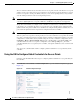
Chapter 7 Controlling Lightweight Access Points Performing a Link Test Figure 7-23 Step 2 Clients Page Hover your cursor over the blue drop-down arrow for the desired client and choose LinkTest. A link test page appears (see Figure 7-24). Note You can also access this page by clicking the MAC address of the desired client and then clicking the Link Test button on the top of the Clients > Detail page. Figure 7-24 Link Test Page This page shows the results of the CCX link test.
Chapter 7 Controlling Lightweight Access Points Configuring Link Latency Using the CLI to Perform a Link Test Use these commands to run a link test using the CLI. 1. To run a link test, enter this command: linktest ap_mac When CCX v4 or later is enabled on both the controller and the client being tested, information similar to the following appears: CCX Link Test to 00:0d:88:c5:8a:d1. Link Test Packets Sent...................................... 20 Link Test Packets Received...............................
Chapter 7 Controlling Lightweight Access Points Configuring Link Latency Note Link latency calculates the CAPWAP response time between the access point and the controller. It does not measure network latency or ping responses. The controller displays the current round-trip time as well as a running minimum and maximum round-trip time. The minimum and maximum times continue to run as long as the controller is up or can be cleared and allowed to restart.
Chapter 7 Controlling Lightweight Access Points Configuring Link Latency Step 8 When the All APs > Details for page reappears, click the Advanced tab again. The link latency results appear below the Enable Link Latency check box: • Current—The current round-trip time (in milliseconds) of CAPWAP heartbeat packets from the access point to the controller and back.
Chapter 7 Controlling Lightweight Access Points Configuring Power over Ethernet Step 3 To clear the current, minimum, and maximum link latency statistics on the controller for a specific access point, enter this command: config ap link-latency reset Cisco_AP Step 4 To view the results of the reset, enter this command: show ap config general Cisco_AP Configuring Power over Ethernet When an access point that has been converted to lightweight mode (such as an AP1131 or AP1242) or a 1250 series access po
Chapter 7 Controlling Lightweight Access Points Configuring Power over Ethernet Table 7-3 shows the maximum transmit power settings for 1250 series access points using PoE. Table 7-3 Maximum Transmit Power Settings for 1250 Series Access Points Using PoE Data Rates 2.4 GHz 802.11b 1 — 20 20 20 802.11g 1 — 17 17 17 802.11n MCS 0-7 1 Disabled 17 17 17 2 Enabled (default) Disabled 14 (11 per Tx) 20 (17 per Tx) 802.11n MCS 8-15 2 — Disabled 14 (11 per Tx) 20 (17 per Tx) 802.
Chapter 7 Controlling Lightweight Access Points Configuring Power over Ethernet The PoE Status field shows the power level at which the access point is operating: High (20 W), Medium (16.8 W), or Medium (15.4 W). This field is not configurable. The controller auto-detects the access point’s power source and displays the power level here. Note Step 3 This field applies only to 1250 series access points that are powered using PoE.
Chapter 7 Controlling Lightweight Access Points Configuring Power over Ethernet • Override—This option allows the access point to operate in high-power mode without first verifying a matching MAC address. It is acceptable to use this option if your network does not contain any older Cisco 6-Watt switches that could be overloaded if connected directly to a 12-Watt access point.
Chapter 7 Controlling Lightweight Access Points Configuring Flashing LEDs The Power Type/Mode field shows “degraded mode” if the access point is not operating at full power. • To view the controller’s trap log, enter this command: show traplog If the access point is not operating at full power, the trap contains “PoE Status: degraded operation.” Configuring Flashing LEDs Controller software release 4.0 or later enables you to flash the LEDs on an access point in order to locate it.
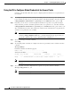
Chapter 7 Controlling Lightweight Access Points Viewing Clients Figure 7-27 Clients Page This page lists all of the clients that are associated to the controller’s access points. It provides the following information for each client: • The MAC address of the client • The name of the access point to which the client is associated • The name of the WLAN used by the client • The type of client (802.11a, 802.11b, 802.11g, or 802.
Chapter 7 Controlling Lightweight Access Points Viewing Clients Figure 7-28 b. Check one or more of the following check boxes to specify the criteria used when displaying clients: • MAC Address—Enter a client MAC address. Note c. Note Step 3 Search Clients Page When you enable the MAC Address filter, the other filters are disabled automatically. When you enable any of the other filters, the MAC Address filter is disabled automatically. • AP Name—Enter the name of an access point.
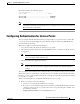
Chapter 7 Controlling Lightweight Access Points Viewing Clients Figure 7-29 Clients > Detail Page Cisco Wireless LAN Controller Configuration Guide OL-17037-01 7-77
Chapter 7 Controlling Lightweight Access Points Viewing Clients This page shows the following information: • The general properties of the client • The security settings of the client • The QoS properties of the client • Client statistics • The properties of the access point to which the client is associated Using the CLI to View Clients Use these CLI commands to view client information. • To see the clients associated to a specific access point, enter this command: show client ap {802.
Chapter 7 Controlling Lightweight Access Points Viewing Clients Diagnostics Capability........................... S69 Capability................................... Mirroring........................................ QoS Level........................................ ...
Chapter 7 Controlling Lightweight Access Points Viewing Clients Cisco Wireless LAN Controller Configuration Guide 7-80 OL-17037-01