C H A P T E R 3 Installing the Cisco VG224 Voice Gateway This chapter contains the procedures for installing your Cisco VG224 voice gateway and consists of the following sections: Tip • Safety Recommendations, page 3-2 • Site Log, page 3-3 • Keeping Track–Checklist, page 3-4 • Mounting Tools and Equipment, page 3-5 • Unpacking and Inspection, page 3-5 • Rack-Mounting the Chassis, page 3-6 • Wall-Mounting the Chassis, page 3-9 • Bench-Top Installation, page 3-11 • Installing the Ground C
Chapter 3 Installing the Cisco VG224 Voice Gateway Safety Recommendations Safety Recommendations The following information is included to alert you to safety recommendations and best practices when working with this equipment. Maintaining Safety with Electricity Follow these guidelines when working on equipment powered by electricity. Warning Do not work on the system or connect or disconnect cables during periods of lightning activity.
Chapter 3 Installing the Cisco VG224 Voice Gateway Site Log • Look carefully for possible hazards in your work area, such as moist floors, ungrounded power extension cables, and missing safety grounds. • If an electrical accident occurs, proceed as follows: – Use caution; do not become a victim yourself. – Turn off power to the system. – If possible, send another person to get medical aid. Otherwise, assess the condition of the victim and then call for help.
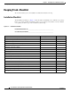
Chapter 3 Installing the Cisco VG224 Voice Gateway Keeping Track–Checklist Keeping Track–Checklist We recommend that you use an installation checklist and maintain a Site Log. Installation Checklist The Installation Checklist (see Figure 3-1) lists the tasks for installing a Cisco VG224 voice gateway. Print a copy of this checklist and mark the entries as you complete each task. For each Cisco VG224 voice gateway, include a copy of the checklist in your Site Log.
Chapter 3 Installing the Cisco VG224 Voice Gateway Mounting Tools and Equipment Mounting Tools and Equipment Obtain the following tools and parts to install a Cisco VG224 voice gateway: • Standard flat-blade screwdriver as required for attaching brackets to rack or wall • Phillips screwdriver for attaching brackets to a Cisco VG224 voice gateway • Mounting brackets and screws for 24-inch rack, if required – Four telco machine screws, for installing the chassis in a rack (use the screw size required b
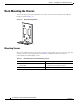
Chapter 3 Installing the Cisco VG224 Voice Gateway Rack-Mounting the Chassis Rack-Mounting the Chassis Your chassis ships with a pair of brackets for use with a 19-inch rack or mounting on the wall. The bracket is shown in Figure 3-2. Quick Mounting Bracket 88815 Figure 3-2 Mounting Screws Two sets of mounting screws are provided, in separate packages. Take care to use each screw type, and washers as needed, in the appropriate locations.
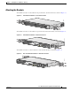
Chapter 3 Installing the Cisco VG224 Voice Gateway Rack-Mounting the Chassis Attaching the Brackets To install the chassis in a rack with the front panel forward, attach the brackets as shown in Figure 3-3. 19-Inch Rack Installation—Front Panel Forward 95915 Figure 3-3 CISCO VG 224 To install the chassis in a rack with the rear panel forward, attach the brackets as shown in Figure 3-4.
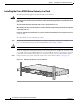
Chapter 3 Installing the Cisco VG224 Voice Gateway Rack-Mounting the Chassis Installing the Cisco VG224 Voice Gateway in a Rack The following warning applies only when the unit is rack-mounted: Warning To prevent bodily injury when mounting or servicing this unit in a rack, you must take special precautions to ensure that the system remains stable. The following guidelines are provided to ensure your safety: This unit should be mounted at the bottom of the rack if it is the only unit in the rack.
Chapter 3 Installing the Cisco VG224 Voice Gateway Wall-Mounting the Chassis Wall-Mounting the Chassis The following warning applies only when the unit is wall-mounted: Warning This unit is intended to be mounted on a wall. Please read the wall-mounting instructions carefully before beginning installation. Failure to use the correct hardware or to follow the correct procedures could result in a hazardous situation to people and damage to the system.
Chapter 3 Installing the Cisco VG224 Voice Gateway Wall-Mounting the Chassis Note For attaching to a wall stud, each bracket requires two #10 wood screws (round- or pan-head) with #10 washers, or two #10 washer-head screws. The screws must be long enough to penetrate at least 3/4 inch (20 mm) into supporting wood or metal wall stud. Note For hollow-wall mounting, each bracket requires two wall anchors with washers. Wall anchors and washers must be size #10.
Chapter 3 Installing the Cisco VG224 Voice Gateway Bench-Top Installation 1 Wall 3 Wall stud 2 Bracket 4 Keyhole for starter screw Bench-Top Installation Step 1 Caution Verify that there is a suitable AC power outlet available. Do not plug this unit into an AC outlet that does not have a UL-certified receptacle that is properly tied into building ground. Step 2 Place the four rubber feet (from the accessory kit) in the four indentations on the underside of the chassis.
Chapter 3 Installing the Cisco VG224 Voice Gateway Installing the Ground Connection • For EN/IEC 60950-compliant grounding, use size AWG 18 (1 mm2) or larger wire and an appropriate user-supplied ring terminal. To ground the chassis, follow this procedure: Step 1 Tip Locate a suitable ground location.
Chapter 3 Installing the Cisco VG224 Voice Gateway Installing the Ground Connection Figure 3-10 NEBS-Compliant Chassis Ground Connection Using Ground Lug VG224-24 FXS 95919 Ground lug Figure 3-11 Chassis Ground Connection Using Ring Terminal VG224-24 103513 FXS Ring terminal attachment Cisco VG224 Voice Gateway Hardware Installation Guide OL-5006-04 3-13
Chapter 3 Installing the Cisco VG224 Voice Gateway Connecting Cables Connecting Cables For cables not included with your Cisco VG224 voice gateway, pinout information is in Appendix A, “Cable Specifications and Information.” Cisco VG224 voice gateway ports are color-coded for identification. Warning Do not work on the system or connect or disconnect cables during periods of lightning activity.
Chapter 3 Installing the Cisco VG224 Voice Gateway Connecting Cables LAN and Power Cables These cables and connections are described in Table 3-3 and in Figure 3-12.
Chapter 3 Installing the Cisco VG224 Voice Gateway Connecting Cables Connecting the Input Power Caution The Cisco VG224 voice gateway chassis provides inputs for both AC and DC power. Design your installation to use only one type of power. Do not use AC and DC power at the same time. If you do, the unit stops operating, and you need to reboot it with only a single power source. Cable Use the AC power cable.
Chapter 3 Installing the Cisco VG224 Voice Gateway Connecting Cables Connecting the Auxiliary Port to a Modem Use the procedure in this section to connect the auxiliary port to a modem. Cable Use an RJ-45-to-DB25 auxiliary cable (labeled Modem). For pinouts, see Table A-3 on page A-5 and Table A-4 on page A-5 in Appendix A, “Cable Specifications and Information.” Procedure Step 1 Connect the cable from the auxiliary port (black) to the DB-25 port on the modem. (See item 6 in Figure 3-12 on page 3-15.
Chapter 3 Installing the Cisco VG224 Voice Gateway Connecting Cables Voice Cables Warning For connections outside the building where the equipment is installed, the following ports must be connected through an approved network termination unit with integral circuit protection. FXS/T3/E3 Statement 1044 Warning This equipment contains a ring signal generator (ringer), which is a source of hazardous voltage.
Chapter 3 Installing the Cisco VG224 Voice Gateway Connecting Cables Connecting the Analog Voice Interface to a Distribution Panel To connect the multiport analog voice interface to a distribution panel, which connects to telephones, faxes, or analog PBX equipment, use the following procedure. (See Figure 3-14.) Cable Use an RJ-21 cable with Amphenol 50-pin connectors (not included). For RJ-21X/CA21A pinouts, see Table A-5 on page A-6 in Appendix A, “Cable Specifications and Information.
Chapter 3 Installing the Cisco VG224 Voice Gateway Ports, Connectors, and Pinouts Ports, Connectors, and Pinouts Table 3-4 summarizes the cable connections between Cisco VG224 voice gateway and the network and user interfaces. Find the port and the equipment or network type in the table; then look at the applicable pinout table in Appendix A, “Cable Specifications and Information.
Chapter 3 Installing the Cisco VG224 Voice Gateway Connecting Backup Power Connecting to a Remote ASCII Terminal To link a Cisco VG224 voice gateway to a remote ASCII terminal, such as a VT100, use the following procedure: Step 1 Connect the remote ASCII terminal and modem. Step 2 Set the terminal requirements: 9600 baud 8 data bits 1 stop bit no parity no flow control.
Chapter 3 Installing the Cisco VG224 Voice Gateway Connecting Backup Power Figure 3-15 Connecting a Battery Backup to a DC-Powered Cisco VG224 Cisco VG224 voice gateway AC wall plug Battery backup XS 103120 VG224-24F DC plug Caution Note Use a backup battery only if you are not using AC to power your Cisco VG224 voice gateway. Do not use AC and DC power at the same time. If you do, the unit stops operating, and you need to reboot it with only a single power source.
Chapter 3 Installing the Cisco VG224 Voice Gateway Connecting Backup Power Connecting a UPS to an AC-Powered Cisco VG224 Connect an uninterruptible power supply to the AC input on your Cisco VG224 voice gateway. Before you install a UPS, be sure to read the installation instructions for the UPS. Figure 3-17 shows a setup using a UPS. Note Figure 3-17 shows one possible setup; please review your UPS documents before setting up your system.
Chapter 3 Installing the Cisco VG224 Voice Gateway Connecting Backup Power Cisco VG224 Voice Gateway Hardware Installation Guide 3-24 OL-5006-04