Customer Order Number: Documentation Part Number: DOC-782881= 78-2881-01 VIP-4R/4T Installation and Configuration Product Number VIP-4R/4T(=) This configuration note is a standalone publication that provides instructions for installing, configuring, and maintaining the Versatile Interface Processor (VIP) in your Cisco 7000 series and Cisco 7500 series routers.
Table of Contents Table of Contents This configuration note includes the following sections: • • If You Need More Configuration Information Versatile Interface Processor Functions, page 3 — What is the VIP?, page 3 Note The following section contains important information about the latest Cisco IOS release.
Versatile Interface Processor Functions For additional information on configuring the Cisco 7000 series or Cisco 7500 series router, the following documentation resources are available to you: • UniverCD This publication and all other Cisco Systems publications are available on UniverCD, which is Cisco’s online library of product information. UniverCD is updated and shipped monthly, so it might be more up to date than printed documentation.
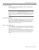
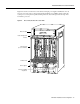
Versatile Interface Processor Functions Note The VIP port adapters themselves do not support OIR, nor are they FRUs. The VIP uses a Reduced Instructions Set Computing (RISC), Mips 4600 processor for high performance, and has an internal operating frequency of 100 megahertz (MHz) and a 50-MHz system bus interface. The VIP has 8 megabytes (MB) of dynamic random access memory (DRAM) as the default DRAM configuration. Figure 1 shows a VIP-4R/4T.
Versatile Interface Processor Functions VIP Software Prerequisites The VIP requires that the host Cisco 7000 series and Cisco 7500 series router is running Cisco Internetwork Operating System (Cisco IOS) Release 11.1(1) or later, or a Cisco-approved beta version of Cisco IOS Release 11.1. Note The latest Cisco IOS release is available via anonymous File Transfer Protocol (FTP) from ftp/beta111_dir@ftp.cisco.com.
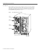
Versatile Interface Processor Functions Cisco 7000 Series Figure 2 and Figure 3 show the rear of the Cisco 7000 series routers: the seven-slot Cisco 7000 and the five-slot Cisco 7010, respectively. In the Cisco 7000 series, two slots are reserved for the SP (or SSP) and RP, or for the 7000 Series Route Switch Processor (RSP7000) and the 7000 Series Chassis Interface (RSP7000CI). The remaining slots are for interface processors: slots 0 through 4 in the Cisco 7000, and slots 0 through 2 in the Cisco 7010.
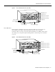
Versatile Interface Processor Functions Figure 3 Cisco 7010, Interface Processor End RSP7000CI slot 4 RSP7000 slot 3 CO NS AU X.
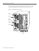
Versatile Interface Processor Functions Figure 5 shows the rear of the seven-slot Cisco 7507 router. In the Cisco 7507, up to two slots (2 and 3) are reserved for the Route Switch Processor (RSP2), which contains the system processor and performs packet switching functions. Slots 0 and 1 and 4 through 6 are for interface processors.
Versatile Interface Processor Functions Figure 6 shows the rear of the Cisco 7513 with two AC-input power supplies installed. Two slots (6 and 7) are reserved for the second generation Route Switch Processor (RSP2), which contains the system processor and performs packet switching functions. Slots 0 through 5 and 8 through 12 are for interface processors.
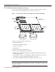
Versatile Interface Processor Functions VIP Port Adapter Hardware Configuration Overview The port adapters attach to the VIP motherboard. (See Figure 7.) Each port adapter contains the physical connections for the VIP interface types to connect to your network.
Versatile Interface Processor Functions Caution To prevent system problems, do not remove port adapters from the VIP motherboard or attempt to install other port adapters on the VIP motherboard. VIP Microcode Overview The VIP microcode (firmware) is an image that provides card-specific software instructions. A Flash memory device in socket U17 of the VIP contains the default microcode boot image.
Versatile Interface Processor Functions Safety Guidelines Following are safety guidelines that you should follow when working with any equipment that connects to electrical power or telephone wiring. Electrical Equipment Guidelines Follow these basic guidelines when working with any electrical equipment: • Before beginning any procedures requiring access to the chassis interior, locate the emergency power-off switch for the room in which you are working.
Versatile Interface Processor Functions • • Handle carriers by the handles and carrier edges only; avoid touching the board or connectors. • Avoid contact between the processor module and clothing. The wrist strap only protects the board from ESD voltages on the body; ESD voltages on clothing can still cause damage. • Never attempt to remove the printed circuit board from the metal interface processor carrier.
Versatile Interface Processor Functions The system brings on line only interfaces that match the current configuration and were previously configured as up; all others require that you configure them with the configure command. OIR functionality enables you to add, remove, or replace interface processors with the system online, which provides a method that is seamless to end users on the network, maintains all routing information, and ensures session preservation.
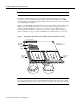
Versatile Interface Processor Functions Figure 8 Ejector Levers and Captive Installation Screws on the VIP (Horizontal Orientation Shown) Interface processor card slot Ejector lever Interface processor card carrier guide (black) a b Captive installation screw H1984 c Note The VIP is oriented horizontally in the Cisco 7010 and Cisco 7505 and vertically in the Cisco 7000, Cisco 7507, and Cisco 7513.
Versatile Interface Processor Functions VIP Installation The following sections describe the procedures for removing or installing a VIP in the Cisco 7000 series and Cisco 7500 series routers. The functionality is the same for each router model; therefore, the term the chassis will be used except where specific model issues arise. The OIR function allows you to install and remove a VIP without first shutting down the system; however, you must follow the instructions carefully.
Versatile Interface Processor Functions Figure 9 shows proper handling of an interface processor during installation. Handling Processor Modules for Installation and Removal (Horizontal Orientation Shown) H4714 Figure 9 Captive installation screws To remove a VIP, follow these steps: Step 1 If you are replacing a failed VIP, disconnect all cables from the VIP ports; however, if you are only moving a VIP to another slot, this step is not necessary.
Versatile Interface Processor Functions Installing a VIP The VIP slides into the open interface processor slot and connects directly to the backplane. The interface processors are keyed to guide pins on the backplane, so the VIP can be installed only in an interface processor slot. Figure 8 shows the functional details of inserting an interface processor and using the ejector levers. Figure 9 shows proper handling of an interface processor during installation.
Versatile Interface Processor Functions Checking the Installation and Verifying VIP Status You can use the configure command to configure a VIP interface. To use the configure command, enter the privileged level of the EXEC command interpreter with the enable command. The system will prompt you for a password if one has been set. The system prompt for the privileged level ends with a pound sign (#) instead of an angle bracket (>).
Versatile Interface Processor Functions The following example display shows the events logged by the system as a new VIP is inserted in slot 3. (Serial interfaces are used in the following examples.
Versatile Interface Processor Functions If an error message is displayed on the console terminal, refer to the System Error Messages publication for error message definitions. If you experience other problems that you are unable to solve, contact a service representative for assistance. This completes the VIP installation. If you installed a new VIP or if you installed a replacement VIP with an additional port, you must now configure the new interface as described in the following section.
Versatile Interface Processor Functions The show controllers cbus command displays the internal status of each interface processor, including the slot location, the card hardware version, and the currently-running microcode version. It also lists each interface (port) on each interface processor including the logical interface number, interface type, physical (slot/port adapter/port) address, and hardware (station address) of each interface.
Versatile Interface Processor Functions Upgrading VIP Microcode The Cisco 7000 series and the Cisco 7500 series support downloadable microcode, which enables you to upgrade microcode versions without having to physically replace the microcode Flash memory device on the board. You can download new microcode versions and store multiple versions in Flash memory, and you can boot from them just as you can with the system software images.
Versatile Interface Processor Functions Follow these steps to download (copy) a microcode version from a TFTP server to Flash memory. Step 1 To display the total amount of Flash memory present, its location, any files that currently exist in Flash memory and their size, and the amount of Flash memory remaining, use the show flash command. Following is an example of the output that is displayed: Router# show flash -#- ED --type-- --crc--- -seek-- nlen -length- -----date/time------ name 1 ..
Versatile Interface Processor Functions Step 5 To ensure that the new microcode is used when you reboot the system, add the appropriate commands to the configuration file. To modify the configuration file, enter the configure terminal command, as follows: Router# config t Enter configuration commands, one per line. Router(config)# End with CNTL/Z. Step 6 Specify that you are changing the microcode for the VIP (microcode vip), and that it will load from Flash memory (flash).
Versatile Interface Processor Functions Upgrading and Replacing DRAM SIMMs VIPs are shipped with 8 megabytes (MB) of dynamic random-access memory (DRAM) as the default DRAM configuration. Depending on memory requirements, you might need to upgrade the amount of DRAM by replacing the DRAM SIMMs on the VIP. You also might need to replace a single SIMM in the case of a diagnosed DRAM SIMM failure. Note DRAM SIMMs should be upgraded or replaced in the field by a Cisco-certified maintenance provider.
Versatile Interface Processor Functions Following is the procedure for replacing or upgrading DRAM SIMMs. Step 1 Attach an ESD-preventive wrist strap between you and an unpainted chassis or VIP surface. Step 2 Disconnect all cables from the VIP and remove it from the chassis using the procedure in the section “Removing a VIP” on page 16. Step 3 Place the VIP on a flat surface (preferably an antistatic mat or foam), and turn it so the face plate is away from you and the connector edge is toward you.
Versatile Interface Processor Functions Step 5 Remove a SIMM by pulling outward on the connectors to unlatch it, as shown in the enlargement in Figure 12. Be careful not to break the holders on the SIMM connector. Figure 12 Removing and Replacing DRAM SIMMs Faceplate edge of the system card Pull the tabs away with your thumbs, bracing your forefingers against the posts. Raise the SIMM to a vertical position.
VIP Port Adapter Functions VIP Port Adapter Functions The following sections discuss the port adapters used with the VIP: • • 4R Port Adapter 4T Port Adapter, page 45 4R Port Adapter The following sections discuss the 4R port adapter, which is shown in Figure 13.
VIP Port Adapter Functions Token Ring Overview The following sections describe Token Ring specifications, physical connections, connection equipment, and cables and connectors. Figure 14 shows the 4R port adapter installed on the VIP-4R/4T.
VIP Port Adapter Functions The IBM Token Ring specifies a star topology, with all end stations connected through a device called a multistation access unit (MSAU). IEEE 802.5 does not specify any topology, although most implementations are based on a star configuration with end stations attached to a device called a media access unit (MAU). Also, IBM Token Ring specifies twisted-pair cabling, whereas IEEE 802.5 does not specify media type.
VIP Port Adapter Functions Figure 15 Token Ring Network Physical Connections MAU or MSAU Ring in 1 2 3 4 5 6 MAU or MSAU 7 8 Ring out Ring in 1 2 3 Stations 2 3 4 5 5 6 7 8 Ring out 7 8 Ring out Stations Patch cables MAU or MSAU Ring in 1 4 6 7 Ring 8 out MAU or MSAU Ring in 1 2 3 4 5 6 Stations Stations H2058 Lobe cables Token Ring Connection Equipment You will need an 802.
VIP Port Adapter Functions Token Ring Distance Limitations The maximum transmission distance is not defined for IEEE 802.5 (Token Ring) networks. Shielded twisted-pair (STP) cabling is most commonly used for rates of 4 and 16 Mbps. Twisted-pair cabling is more susceptible to interference than other types of cabling; therefore, the network length and repeater spacing should be planned accordingly.
VIP Port Adapter Functions 4R Port Adapter Receptacles, Cables, and Pinouts A network interface cable provides the connection between the 9-pin Token Ring receptacles on the 4R port adapter and a media access unit (MAU). The 9-pin connector at the 4R port adapter end, and the MAU connector at the network end, are described in the section “Token Ring Connection Equipment” on page 32.
VIP Port Adapter Functions 4R Port Adapter Receptacle Pinout Table 2 lists the pinout for the DB-9 receptacle used on the 4R port adapter. Table 2 Token Ring Signals Pin Signal 1 Ring-In B 5 Ring-Out A 6 Ring-In A 9 Ring-Out B 10 and 11 Ground Attaching 4R Port Adapter Interface Cables The Token Ring ports on the 4R port adapter run at either 4- or 16 Mbps. You need one Token Ring interface cable for each 4R port adapter interface you want to use.
VIP Port Adapter Functions Step 2 Attach the port adapter end of a Token Ring interface cable, or other connection equipment, to the interface port. (See Figure 19). Note Port adapters have a handle attached, but this handle is not shown to allow a full view of detail on each port adapter’s faceplate.
VIP Port Adapter Functions Using the EXEC Command Interpreter Before you use the setup or the configure command, you must have privileged access to the EXEC command interpreter. The system prompt for the privileged level ends with a pound sign (#) instead of an angle bracket (>). The EXEC enable command allows access to the privileged level, prompting for a password if one has been set with the enable-password configuration command. Follow these steps to enter the privileged level of the EXEC.
VIP Port Adapter Functions Note After you start the setup command facility, the system runs through the entire configuration process; you cannot quit out of it. To make a change or correct a mistake, press the Return key at each prompt, answer no when asked if you want to save the configuration, and restart the setup facility.
VIP Port Adapter Functions Step 5 To use the configuration you created, enter yes. To discard the configuration file and begin the configuration process again, enter no. If you entered yes at the prompt, the following message is displayed: Press RETURN to get started! The configuration process is complete. Proceed to the section “Checking the Configuration” on page 44. It provides show commands you can use to display and verify the configuration information.
VIP Port Adapter Functions Figure 20 shows some of the slot port adapter and interface ports of a sample Cisco 7505 system. For example, the addresses for the 4R interface ports on the first port adapter are 3/0/0 through 3/0/3 (chassis slot 3, port adapter slot 0, and interface ports 0 through 3). The first port adapter slot number is always 0. The second port adapter slot number is always 1. The individual interface port numbers always begin with 0.
VIP Port Adapter Functions Following is an example of how the show interfaces [type slot/port adapter/port] command displays status information (including the physical slot and port address) for the interfaces you specify. In these examples, most of the status information for each interface is omitted, and the four Token Ring interfaces (0–3) are in chassis slot 3, in port adapter slot 1. (Interfaces are administratively shut down until you enable them.
VIP Port Adapter Functions Table 4 4R Slot, Port Adapter, and Port Numbers in a Cisco 7010 Slot 0/ Adapter 0/ Port n Slot 1/ Adapter 0/ Port n Slot 2/ Adapter 0/ Port n 0/0/0 1/0/0 2/0/0 0/0/1 1/0/1 2/0/1 0/0/2 1/0/2 2/0/2 0/0/3 1/0/3 2/0/3 Table 5 4R Slot, Port Adapter, and Port Numbers in a Cisco 7505 Slot 0/ Adapter 0/ Port n Slot 1/ Adapter 0/ Port n Slot 2/ Adapter 0/ Port n Slot 3/ Adapter 0/ Port n 0/0/0 1/0/0 2/0/0 3/0/0 0/0/1 1/0/1 2/0/1 3/0/1 0/0/2 1/0/2 2/0/2 3/
VIP Port Adapter Functions With the show interfaces type slot/port adapter/port command, use arguments such as the interface type (Token Ring, and so forth) and the slot, port adapter, and port numbers (slot/port adapter/port) to display information about a specific serial interface only.
VIP Port Adapter Functions Step 7 When all new interfaces are configured, press Ctrl-Z (hold the Control key down and press the Z key). Step 8 Write the new configuration to memory by entering the following: Router# copy running-config startup-config [OK] Router# Step 9 Enter quit to exit Configuration mode: Router# quit You have now completed configuring the Token Ring interfaces. Check the configuration as described in the section “Checking the Configuration.
VIP Port Adapter Functions 4T Port Adapter The following sections discuss the 4T port adapter, which is shown in Figure 21.
VIP Port Adapter Functions EIA/TIA-232, which is by far the most common interface standard in the U.S., supports unbalanced circuits at signal speeds up to 64 kbps. EIA/TIA-449, which supports balanced (EIA/TIA-422) and unbalanced (EIA/TIA-423) transmissions, is a faster (up to 2 Mbps) version of EIA/TIA-232 that provides more functions and supports transmissions over greater distances. The EIA/TIA-449 standard was intended to replace EIA/TIA-232, but it was not widely adopted.
VIP Port Adapter Functions 4T Port Adapter Specifications The following sections discuss specifications related to the 4T synchronous serial port adapter. Figure 22 shows the 4T port adapter installed on the VIP-4R/4T.
VIP Port Adapter Functions Serial Distance Limitations Serial signals can travel a limited distance at any given bit rate; generally, the slower the baud rate, the greater the distance. All serial signals are subject to distance limits beyond which a signal degrades significantly or is completely lost. Table 8 lists the IEEE-recommended maximum speeds and distances for each 4T port adapter serial interface type. The recommended maximum rate for V.35 is 2.048 Mbps.
VIP Port Adapter Functions Figure 23 EIA/TIA-232 Adapter Cable Connectors, Network End DCE H1343a DTE EIA/TIA-449 Connections The router (VIP) end of all EIA/TIA-449 adapter cables is a high-density 60-pin plug. The opposite (network) end of the adapter cable provides a standard 37-pin D-shell connector, which is commonly used for EIA/TIA-449 connections. Figure 24 shows the connectors at the network end of the adapter cable.
VIP Port Adapter Functions X.21 Connections The router (VIP) end of all X.21 adapter cables is a high-density 60-pin plug. The opposite (network) end of the adapter cable is a standard DB-15 connector. Figure 26 shows the connectors at the network end of the X.21 adapter cable. X.21 cables are available as either DTE (DB-15 plug) or DCE (DB-15 receptacle). Figure 26 X.
VIP Port Adapter Functions Note The VIP is oriented horizontally in the Cisco 7010 and Cisco 7505, and vertically in the Cisco 7000, the Cisco 7507, and the Cisco 7513. The following conditions must be met before the enabled LED goes on: • • • The 4T interface is correctly connected to the backplane and receiving power. The 4T-equipped VIP contains a valid microcode version that has been downloaded successfully. The bus recognizes the 4T-equipped VIP.
VIP Port Adapter Functions The network end of the cable is an industry-standard connector for the type of electrical interface that the cable supports. For most interface types, the adapter cable for DTE mode uses a plug at the network end, and the cable for DCE mode uses a receptacle at the network end. Exceptions are V.35 adapter cables, which are available with either a V.
VIP Port Adapter Functions Figure 29 shows the serial port adapter cables for connection from the 4T port adapters to your network. Figure 29 Serial Port Adapter Cables H5763 (PA-4T port adapter) Router connections EIA/TIA-232 EIA/TIA-449 V.35 X.21 EIA-530 Network connections at the modem or CSU/DSU Metric (M3) thumbscrews are included with each port adapter cable to allow connections to devices that use metric hardware.
VIP Port Adapter Functions The tables that follow list the signal pinouts for both the DTE and DCE mode serial port adapter cables, for each of the following 4T port adapter interface types: • • • • • EIA/TIA-232 pinout, Table 10 EIA/TIA-449 pinout, Table 11 X.21 pinout, Table 12 V.
VIP Port Adapter Functions Table 11 EIA/TIA-449 Adapter Cable Signals DTE Cable DCE Cable HD1 VIP End, 60-Position Plug Network End, DB-37 Plug VIP End, HD 60-Position Plug Network End, DB-37 Receptacle Signal Pin Pin Signal Signal Pin Pin Signal Shield ground 46 1 Shield ground Shield ground 46 1 Shield ground TxD/RxD+ 11 —> 4 SD+ RxD/TxD+ 28 <— 4 SD+ TxD/RxD– 12 —> 22 SD– RxD/TxD– 27 <— 22 SD– TxC/RxC+ 24 <— 5 ST+ TxCE/TxC+ 13 —> 5 ST+ TxC/RxC– 23
VIP Port Adapter Functions Table 12 X.
VIP Port Adapter Functions Table 13 V.
VIP Port Adapter Functions Table 14 EIA-530 DTE Adapter Cable Signals VIP End, HD1 60-Position Plug Network End, DB-25 Plug Signal Pin Pin Signal Shield ground 46 1 Shield ground TxD/RxD+ 11 —> 2 TxD+ TxD/RxD– 12 —> 14 TxD– RxD/TxD+ 28 <— 3 RxD+ RxD/TxD– 27 <— 16 RxC– RTS/CTS+ 9 —> 4 RTS+ RTS/CTS– 10 —> 19 RTS– CTS/RTS+ 1 <— 5 CTS+ CTS/RTS– 2 <— 13 CTS– DSR/DTR+ 3 <— 6 DSR+ DSR/DTR– 4 <— 22 DSR– DCD/DCD+ 5 <— 8 DCD+ DCD/DCD– 6 <— 10 DCD
VIP Port Adapter Functions Attaching 4T Port Adapter Interface Cables On a single 4T port adapter, you can use up to four synchronous-serial connections. Connect serial cables to the 4T port adapter as follows: Step 1 Attach the appropriate serial cable directly to the receptacle on the 4T port adapter and tighten the strain-relief screws. (See Figure 30.
VIP Port Adapter Functions Configuring the 4T Interfaces If you installed a new VIP or if you want to change the configuration of an existing interface, you must enter Configuration mode to configure the new interfaces. If you replaced a VIP that was previously configured, the system will recognize the new 4T port adapter interfaces and bring each of them up in their existing configuration.
VIP Port Adapter Functions Interface ports on the 4T port adapter maintain the same address regardless of whether other interface processors are installed or removed. However, when you move a VIP to a different slot, the first number in the address changes to reflect the new slot number. Figure 32 shows some of the slot port adapter and interface ports of a sample Cisco 7505 system.
VIP Port Adapter Functions Following is an example of how the show interfaces [type slot/port adapter/port] command displays status information (including the physical slot and port address) for the interfaces you specify. In these examples, most of the status information for each interface is omitted, and the four serial interfaces (0–3) are in chassis slot 3, in port adapter slot 1. (Interfaces are administratively shut down until you enable them.
VIP Port Adapter Functions Table 16 4T Slot, Port Adapter, and Port Numbers in a Cisco 7010 Slot 0/ Adapter 1/ Port n Slot 1/ Adapter 1/ Port n Slot 2/ Adapter 1/ Port n 0/1/0 1/1/0 2/1/0 0/1/1 1/1/1 2/1/1 0/1/2 1/1/2 2/1/2 0/1/3 1/1/3 2/1/3 Table 17 4T Slot, Port Adapter, and Port Numbers in a Cisco 7505 Slot 0/ Adapter 1/ Port n Slot 1/ Adapter 1/ Port n Slot 2/ Adapter 1/ Port n Slot 3/ Adapter 1/ Port n 0/1/0 1/1/0 2/1/0 3/1/0 0/1/1 1/1/1 2/1/1 3/1/1 0/1/2 1/1/2 2/1/2
VIP Port Adapter Functions With the show interfaces type slot/port adapter/port command, use arguments such as the interface type (serial, and so forth) and the slot, port adapter, and port numbers (slot/port adapter/port) to display information about a specific serial interface only.
VIP Port Adapter Functions The show version (or show hardware) command displays the configuration of the system hardware (the number of each interface processor type installed), the software version, the names and sources of configuration files, and the boot images. Following is an example of the show version command used with a Cisco 7500 series system: Router# show version Cisco Internetwork Operating System Software IOS (tm) GS Software (RSP-A), Version 11.
VIP Port Adapter Functions Following are the acceptable clockrate settings: 1200, 2400, 4800, 9600, 19200 38400, 56000, 64000, 72000, 125000 148000, 500000, 800000, 1000000, 1300000, 2000000 Speeds above 64 kbps (64000) are not appropriate for EIA/TIA-232. On all interface types, faster speeds might not work if your cable is too long. Inverting the Clock Signal Systems that use long cables may experience high error rates when operating at the higher transmission speeds.
VIP Port Adapter Functions Configuring CRCs CRC is an error-checking technique that uses a calculated numeric value to detect errors in transmitted data. All interfaces use a 16-bit CRC by default, but also support a 32-bit CRC. The sender of a data frame divides the bits in the frame message by a predetermined number to calculate a remainder or frame check sequence (FCS).
VIP Port Adapter Functions However, it does not necessarily repoll an interface when you change the adapter cable online. To ensure that the system recognizes the new interface type, shut down and reenable the interface after changing the cable. Perform the following steps to change the mode or interface type of a port by replacing the adapter cable. First replace the cable, then shut down and bring up the interface with the new cable attached so that the system recognizes the new interface.
VIP Port Adapter Functions Using the EXEC Command Interpreter Before you use the configure command, you must enter the privileged level of the EXEC command interpreter with the enable command. The system will prompt you for a password if one has been set. The system prompt for the privileged level ends with a pound sign (#) instead of an angle bracket (>). At the console terminal, enter the privileged level as follows: Step 1 At the user-level EXEC prompt, enter the enable command.
VIP Port Adapter Functions Step 5 To shut down additional interfaces, enter the slot/port address of each additional interface followed by the shutdown command.
VIP Port Adapter Functions Ports are numbered sequentially beginning with either the top port (in the Cisco 7000, Cisco 7507, and Cisco 7513) or the left-most port (in the Cisco 7010, and the Cisco 7505), which is always port (interface) 0. For example, the slot/port adapter/port address of the first interface on a VIP installed in interface processor slot 1 is 1/1/0, and the adjacent port on the same VIP is 1/1/1. The following steps describe a basic configuration.
VIP Port Adapter Functions Checking the Configuration After configuring the new interface, use the show commands to display the status of the new interface or all interfaces. Using Show Commands to Verify the VIP Status The following steps use show commands to verify that the new interfaces are configured and operating correctly. Step 1 Use the show version command to display the system hardware configuration. Ensure that the list includes the new serial interfaces.
VIP Port Adapter Functions Following is an example of a successful ping command to a remote server with the address 1.1.1.10: Router# ping 1.1.1.10 Type escape sequence to abort. Sending 5, 100-byte ICMP Echoes to 1.1.1.10, timeout is 2 seconds: !!!!! Success rate is 100 percent (5/5), round-trip min/avg/max = 1/15/64 ms Router# If the connection fails, verify that you have the correct IP address for the server and that the server is active (powered on), and repeat the ping command.
Cisco Information Online Cisco Information Online Cisco Information Online (CIO) is Cisco Systems’ primary, real-time support channel. Maintenance customers and partners can self-register on CIO to obtain additional content and services. Available 24 hours a day, 7 days a week, CIO provides a wealth of standard and value-added services to Cisco’s customers and business partners.