
Universal Broadband Router Hardware Installation Guide


3-10
Cisco uBR10012 Universal Broadband Router Hardware Installation Guide
OL-18259-01
Chapter 3 Installing the Cisco uBR10012 Router
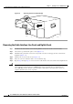
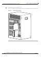
Removing the Power Modules, Fan Assembly, and Line Cards
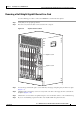
Figure 3-6 Removing the Fan Assembly Module
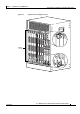
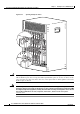
Removing the Cable Interface Line Cards and Uplink Cards
Step 1 To remove the cable interface and network uplink line cards, move to the rear of the chassis.
Step 2 Unscrew the top and bottom captive screws (Figure 3-7).
Step 3 Simultaneously pivot both ejector levers away from each other to disengage the line card from the
backplane (
Figure 3-8).
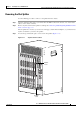
Step 4 Slide the line card out of the slot (see Figure 3-8).
Step 5 Place the card on an antistatic surface or in an antistatic bag.
Step 6 Repeat Step 2 through Step 5 to remove the other cable interface line cards and the network uplink cards.
Caution If you are using the Cisco uBR-MC28C or Cisco uBR-MC16xx line cards, do not attempt to separate or
remove the line cards from the Cisco uBR10-LCP2 adapter card while they are installed in the
Cisco
uBR10012 chassis. The line cards and adapter cards must be removed from the chassis as a
complete unit before they can be separated.
103485
CISCO
10000
CISCO