
Universal Broadband Router Hardware Installation Guide

CHAPTER
3-1
Cisco uBR10012 Universal Broadband Router Hardware Installation Guide
OL-18259-01
3
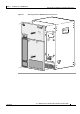
Installing the Cisco uBR10012 Router
This chapter describes the procedures for installing the Cisco uBR10012 universal broadband router in
an equipment rack. It also describes how to connect interface and power cables, the proper way to power
on the system, and installation troubleshooting procedures.
Installation involves doing the following tasks in the following order:
• Preparing the Cisco uBR10012 Router for Rack-Mounting, page 3-2
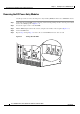
• Removing the Power Modules, Fan Assembly, and Line Cards, page 3-4
• Removing the Half-Height Gigabit Ethernet Line Card and the Slot Splitters, page 3-12
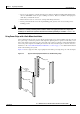
• Attaching the Mounting Brackets, page 3-17
• Installing the Cable Management Brackets (Optional), page 3-21
• Mounting the Chassis in the Rack, page 3-22
• Connecting the Chassis to Ground, page 3-25
• Connecting DC Power to the Cisco uBR10012 Router, page 3-28
• Connecting Alarm Indicators, page 3-31
• Connecting the Console Port and Auxiliary Port, page 3-49
• Reinstalling the Modules, page 3-34
• Installing the Slot Splitter and Half-Height Gigabit Ethernet Line Card, page 3-42
• Connecting the Console Port and Auxiliary Port, page 3-49
• Connecting Network Management Cables, page 3-52
• Connecting Cable Interface Line Cards and Network Uplink Cards, page 3-55
• Replacing the Front Cover, page 3-58
• Powering On the System, page 3-60
• Configuring the Cisco uBR10012 Router at Startup, page 3-62
• Formatting PC Media Cards, page 3-66
Warning
This equipment must be installed and maintained by service personnel as defined by AS/NZS 3260.
Incorrectly connecting this equipment to a general-purpose outlet could be hazardous. The
telecommunications lines must be disconnected 1) before unplugging the main power connector or 2)
while the housing is open, or both.
Statement 1043