
Universal Broadband Router Hardware Installation Guide


1-26
Cisco uBR10012 Universal Broadband Router Hardware Installation Guide
OL-18259-01
Chapter 1 Cisco uBR10012 Universal Broadband Router Overview
Cisco uBR10012 Universal Broadband Router Modules
When two TCC+ cards are installed, they are configured as active and backup (redundant). If the TCC+
card in the first slot is working at system power-up, it automatically becomes the active card and the
TCC+ card in the second slot becomes the backup card. The TCC+ cards monitor each other’s priority
information so that if the active card fails, the active card role is transferred to the redundant backup card
without lose of data.
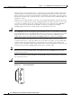
Each TCC+ card contains two RJ-45 connectors on its faceplate labeled Primary and Secondary. These
connectors are for a primary and secondary (redundant) Stratum 3 external clock reference source that
is traceable to a Stratum 1 clock source. The external reference source allows the Cisco
uBR10012
reference clock to be synchronized to the Stratum 1 clock source, providing a free-running
DOCSIS-quality clock reference and time stamp to the cable interface line cards.
Caution The TCC+ card can connect only to a national clock source such as a GPS receiver or BITS clock. The
Cisco uBR10012 router does not support connecting the RJ-45 connectors on the TCC+ cards directly
to an outside plant line or telco-provided T1/E1 clock source. You can use an outside or telco-provided
T1/E1 clock source only by connecting the source to the TCC+ cards using a CSU/DSU or other
equipment that is approved to FCC part 68 and ANSI/UL1950 for the connection to the PSTN.
If present, the primary external clock reference on the active TCC+ card is used. If it is lost, the
secondary clock reference on the active TCC+ card is used. If the active TCC+ card stops functioning,
control is transferred to the backup TCC+ card, which then uses its primary and secondary clock
reference sources. If neither card has a valid clock reference source, the active TCC+ card uses its own
internal clock to provide the DOCSIS-quality clock reference and time stamp.
Note You do not need to provide any external clock reference source to the TCC+ cards. However, you must
always have at least one functioning TCC+ card installed in the Cisco
uBR10012 chassis to ensure
proper systems operation.
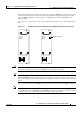
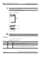
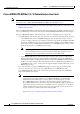
Figure 1-23 shows the faceplate of the TCC+ card. The handle provides for the insertion and removal of
the card from the chassis.
Caution Do not attempt to lift the chassis using one of these handles.
Figure 1-16 TCC+ Card Faceplate
56418