
Universal Broadband Router Hardware Installation Guide


1-24
Cisco uBR10012 Universal Broadband Router Hardware Installation Guide
OL-18259-01
Chapter 1 Cisco uBR10012 Universal Broadband Router Overview
Cisco uBR10012 Universal Broadband Router Modules
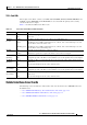
Power Supply Cables
The AC PEM requires different power supply cables, depending on the country of operation. Table 1-8
lists the product order numbers for the power supply cables that are available for the AC PEM for the
Cisco
uBR10012 universal broadband router.
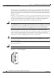
Airflow
The PEMs (both AC and DC) work together with the fan assembly module to ensure that the
Cisco
uBR10012 chassis is properly cooled during normal operation.
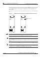
Figure 1-15 shows the airflow through the Cisco uBR10012 chassis when dual PEMs are installed.
Note Figure 1-15 shows the Cisco uBR10012 chassis without the front bezel installed, but the front bezel
should be installed during normal operation so that the air filter in the bezel can filter the incoming air
before it enters the chassis.
Ta b l e 1-8 Power Cables for the AC Power Entry Module for the Cisco uBR10012 Router
Description Product Order Number
Argentina CAB-UBR10-AC-AR
Australia/New Zealand CAB-UBR10-AC-AU
China CAB-UBR10-AC-CH
Europe CAB-UBR10-AC-EU
Italy CAB-UBR10-AC-IT
Japan CAB-UBR10-AC-JP
North America CAB-UBR10-AC-US
United Kingdom CAB-UBR10-AC-UK