
Universal Broadband Router Hardware Installation Guide


1-23
Cisco uBR10012 Universal Broadband Router Hardware Installation Guide
OL-18259-01
Chapter 1 Cisco uBR10012 Universal Broadband Router Overview
Cisco uBR10012 Universal Broadband Router Modules
Tip For fully redundant power protection, use either an uninterruptible power supply (UPS) or a separate
AC-input power source for each AC PEM.
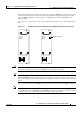
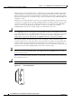
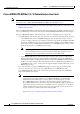
Figure 1-14 shows the front panel of the AC PEM.
Figure 1-14 AC PEM Faceplate
Caution The two handles on the front of the AC PEM are for removing and inserting the PEM into the
Cisco uBR10012 chassis. Do not attempt to lift the Cisco uBR10012 chassis by using these handles.
AC PEM LEDs
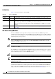
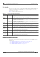
Table 1-7 describes the LEDs on the AC PEM.
62520
POW
ER
FAULT
AC power
cord clips
AC power switch
AC power plug
Ta b l e 1-7 Cisco AC PEM LEDs and Their Functions
LED Status Description
POWER Green The PEM is on, is receiving power from the AC power source, and is providing power to
the Cisco
uBR10012 chassis (normal operations).
FAULT Yellow AC-input power is being received by the PEM, but that the PEM is not supplying power to
the chassis, typically because the PEM’s power switch is turned to the standby position.
If the power switch is in the ON position, the PEM is not operating correctly.