
Universal Broadband Router Hardware Installation Guide


1-22
Cisco uBR10012 Universal Broadband Router Hardware Installation Guide
OL-18259-01
Chapter 1 Cisco uBR10012 Universal Broadband Router Overview
Cisco uBR10012 Universal Broadband Router Modules
DC PEM LEDs
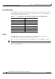
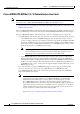
Table 1-6 describes the LEDs on the DC PEM.
AC Power Entry Modules
The Cisco uBR10012 router ships with two AC power entry modules (AC PEMs) that provide a
redundant power supply to the system. One AC PEM can provide sufficient power for a fully configured
chassis, so that if one AC PEM fails, the other automatically begins providing power for the entire router,
without impacting system operations.
Note You must use Cisco IOS Release 12.2(4)XF1, Cisco IOS Release 12.2(4)BC1a, or a later release when
using the AC PEM. If using an earlier release, the show environment command will not correctly
identify the AC PEM’s error messages.
Caution The Cisco uBR10012 router does not support mixing AC and DC PEMs. Both PEMs must be either
AC PEMs or DC PEMs.
The AC PEMs use standard 200–240 VAC (50/60 Hz) input power obtained through power receptacles
on the front panel of each PEM. The two AC PEMs convert the AC power to provide filtered, redundant,
and load shared DC power to the Cisco
uBR10012 chassis.
Caution The AC PEMs cannot be used with a 100–120 VAC input power source.
Tip You do not need to shut down the Cisco uBR10012 router to replace a redundant AC PEM. If you are
replacing both AC PEMs, you can replace one, bring it online, and then replace the other one to avoid
shutting down the system.
Although one AC PEM can provide sufficient power for a fully configured Cisco uBR10012 chassis, the
system should not be run for an extended period of time with only one AC PEM. If an AC PEM fails,
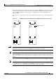
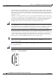
install a replacement AC PEM as soon as possible. For proper airflow (see
Figure 1-15), cooling, and
safety, do not remove the failed unit until the replacement unit is available for installation.
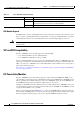
Ta b l e 1-6 Cisco DC PEM LEDs
LED Status Description
POWER Green The DC PEM is powered on, receiving power from the external DC power source, and is
providing power to the Cisco
uBR10012 chassis (normal operation).
FAULT Yellow External DC power is being received by the DC PEM but that the PEM is not supplying power
to the chassis, typically because the PEM’s power switch is turned off.
If the power switch is in the ON position, and the Fault LED lights, the PEM is not operating
correctly
MISWIRE Yellow –48/–60 VDC and RTN (+) wires are reversed (see the “Powering On the System” section on
page 3-60).