
Universal Broadband Router Hardware Installation Guide


1-21
Cisco uBR10012 Universal Broadband Router Hardware Installation Guide
OL-18259-01
Chapter 1 Cisco uBR10012 Universal Broadband Router Overview
Cisco uBR10012 Universal Broadband Router Modules
The optional AC-input power shelf provides DC power to the Cisco uBR10012 router when a DC power
outlet is unavailable or where AC power is desired. For information about the AC-input power shelf,
refer to 2400W AC-Input Power Shelf for the Cisco uBR10012 Universal Broadband Router at the
following URL:
http://www.cisco.com/en/US/docs/cable/cmts/ubr10012/installation/field_replaceable_units/ub10acsh.
html
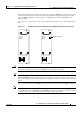
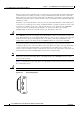
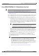
Figure 1-13 DC PEM Faceplate (Original Model) and DC PEM Faceplate with Alarm Connector
Caution The two handles on the DC PEM are for removing and inserting the PEM into the Cisco uBR10012
chassis. Do not attempt to lift the Cisco uBR10012 chassis by using these handles.
Tip When using the external AC-input power shelf and Cisco IOS Release 12.2(4)XF or later release, the
show environment command provides information on whether a power module in the power shelf is
missing, is reporting a fault, is experiencing an over-temperature condition, or is not receiving AC input
power.
If you are not using the optional 2400W AC-input power shelf, the two models of DC PEM are identical.
Note The power supply monitoring cable (product order number UBR10-PWR-MON-CAB=, part number
72-3505-01) for the Cisco
uBR10012 router DC PEMs is not the same cable that is used for the similar
connection on the Cisco AS5850 Universal Gateway (part number 72-2673-01).
POWER
MISWIRE
FAULT
72435
POWER
MISWIRE
FAULT
Alarm connector