
Universal Broadband Router Hardware Installation Guide


1-20
Cisco uBR10012 Universal Broadband Router Hardware Installation Guide
OL-18259-01
Chapter 1 Cisco uBR10012 Universal Broadband Router Overview
Cisco uBR10012 Universal Broadband Router Modules
PRE Module Disposal
The PRE module contains a small lithium battery. Some jurisdictions restrict the ways in which you can
dispose of items containing lithium batteries. In particular, never dispose of lithium batteries or products
containing lithium batteries in an unregulated fire. Other restrictions might apply in your area.
Warning
Ultimate disposal of this product should be handled according to all national laws and regulations.
Statement 1040.
SIP and SPA Compatibility
The Cisco uBR10012 router currently supports the following SIPs:
• Cisco Wideband SIP for the Cisco Wideband SPA
• Cisco 10000 Series SPA Interface Processor-600
The Cisco Wideband SIP can support up to two Cisco Wideband SPAs. The Cisco uBR10012 router can
support up to six SPAs. For more information about the introduction of support for different SIPs and
SPAs, refer to the Cisco uBR10012 Universal Broadband Router SIP and SPA Software Configuration
Guide at the following location:
http://www.cisco.com/en/US/docs/interfaces_modules/shared_port_adapters/configuration/ubr10012/1
2.3_23_bc/sipsp_d3.html
DC Power Entry Modules
The Cisco uBR10012 router ships with two DC power entry modules (DC PEMs) The PEMs receive
–48/–60
VDC power through separate terminal blocks underneath each PEM. The two DC PEMs provide
filtered, redundant, and loadshared DC power to the Cisco
uBR10012 chassis. If one DC PEM fails, the
other PEM immediately begins providing the required power to the system.
Although one DC PEM can provide sufficient power for a fully configured Cisco uBR10012 chassis, the
system should not be run for an extended period time with only one DC PEM. If a DC PEM fails, install
a replacement DC PEM as soon as possible.
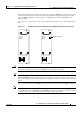
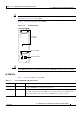
There are two models of the DC PEM. Figure 1-13 shows the DC PEM with the original faceplate (on
the left) and the DC PEM with the connector used for the power supply monitoring cables (on the right).
The power supply monitoring cables connect to the optional 2400W AC-input power shelf.
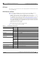
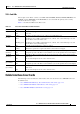
BITS Green BITS input to the PRE is configured and functioning normally.
Yellow BITS input to the PRE is configured, but not functional. For example,
the framer may have detected a Loss of Signal (LOS).
Off BITS input to the PRE4 is not configured.
1. The Cisco uBR10012 router supports PCMCIA flash memory cards of 64 MB or above.
Table 1-5 Cisco PRE LEDs and Cutoff Switch
LEDs/Switch Status Description