
Universal Broadband Router Hardware Installation Guide

1-18
Cisco uBR10012 Universal Broadband Router Hardware Installation Guide
OL-18259-01
Chapter 1 Cisco uBR10012 Universal Broadband Router Overview
Cisco uBR10012 Universal Broadband Router Modules
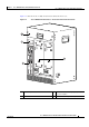
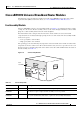
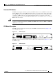
The PRE4 contains a CompactFlash Disk slot (disk0) and 128 MB of onboard flash memory. Figure 1-12
shows the PRE4 faceplate.
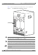
Figure 1-12 PRE4 Faceplate
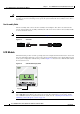
Connector Ports
The faceplate on the PRE contains three ports with RJ-45 connectors:
• Console port—This asynchronous EIA/TIA-232 serial port is used to connect a terminal to the PRE
for local administrative access.
• Auxiliary port (AUX)—This asynchronous EIA/TIA-232 serial port is used to connect a modem to
the PRE for remote administrative access.
• Fast Ethernet port—This Fast Ethernet port is used to connect the PRE to a 10/100Base-T network
management LAN.
Note The Fast Ethernet interface on the PRE module is intended for network management access
and should not be used for WAN connectivity purposes. For WAN connections, use the
appropriate network uplink cards, which take full advantage of the system's
high-performance PXF processing subsystem.
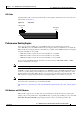
PC Media Card Slots
Two PC media card slots (one CompactFlash Disk slot for the PRE4) can store the Cisco IOS image or
a system configuration file on a PC media card or CompactFlash Disk. The system can also boot from
the software stored on the PC media card or CompactFlash Disk. The PC media card slots support Type
I or Type II cards. See the
“Removing and Installing a PC Media Card” section on page 34 for more
information about inserting and removing PC media cards from the PRE.
211327
PERFORMANCE ROUTING ENGINE
ALARMS
CISCO
10000
ACT
IVITY
LINK
CRITICAL
M
AJO
R
M
IN
OR
ACO
SLOT 0
STATUS
FA
IL
BITS
ETHERNET
AUX
CONSOLE
P/N ESR-PRE4
1 3 7 8
9
2 106 12
11
54
1 Ejector levers 7 ACO (Alarm Cut-off) button
2 Console and Auxiliary ports 8 CompactFlash Disk slot, disk0
3 Network Management Ethernet (NME) port 9 Slot 0 (disk0) LED
4 NME Activity and Link LEDs 10 Status, Fail LEDs
5 Reset button 11 Building Internal Timing Source (BITS) LED
6 Alarms: Critical, Major, Minor LEDs 12 Alphanumeric display