
Universal Broadband Router Hardware Installation Guide

1-14
Cisco uBR10012 Universal Broadband Router Hardware Installation Guide
OL-18259-01
Chapter 1 Cisco uBR10012 Universal Broadband Router Overview
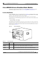
Cisco uBR10012 Universal Broadband Router Modules
Caution Although the fan assembly supports hot-swapping and can be replaced without interruption to system
operation, to prevent overheating, do not operate the system without the fan assembly for more than a
few minutes.
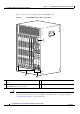
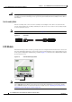
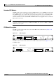
Fan Assembly Cable
The fan assembly cable connects the fan assembly to the backplane. The cable is located inside the
chassis, underneath the fan assembly. Ordinarily the cable is not removed when a fan assembly module
is removed from the chassis.
Note The cable has different connectors on each end. See Figure 1-7
Figure 1-7 Fan Cable
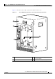
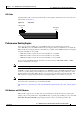
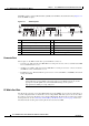
LCD Module
The LCD module provides real-time operating status and configuration information for the chassis and
line cards. The buttons below the screen provide a menu system that allows you to display different parts
of the system configuration without using a terminal.
Figure 1-8 shows the Cisco LCD module without
the chassis front cover.
Figure 1-8 LCD Module Display Panel
Note The LCD module functions depend on the release of the Cisco IOS software running on your
Cisco
uBR10012 router. Refer to the release notes for the Cisco IOS release you are using, and the
Cisco
uBR10012 Software Configuration Guide, for details. See the “Obtaining Documentation and
Submitting a Service Request” section on page xxi.
62338
Male connector Female connector
62391
Keypads