
Universal Broadband Router Hardware Installation Guide

1-13
Cisco uBR10012 Universal Broadband Router Hardware Installation Guide
OL-18259-01
Chapter 1 Cisco uBR10012 Universal Broadband Router Overview
Cisco uBR10012 Universal Broadband Router Modules
Cisco uBR10012 Universal Broadband Router Modules
The following section describes the modules used in the Cisco uBR10012 router. For a list of field
replaceable units (FRUs) used in this chassis, see
“Cisco uBR10012 Router FRU Resources”.
Fan Assembly Module
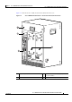
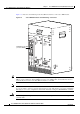
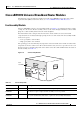
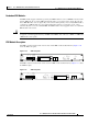
The Cisco uBR10012 router uses a fan assembly module (see Figure 1-6) containing four fans to supply
cooling air to the chassis. The fan assembly connects to the chassis through a blind mate connector that
plugs into a cable assembly and then into the chassis backplane.
Four internal fans draw cooling air into the front of the chassis and direct it across the internal
components. The air is exhausted through openings in the rear of the chassis. The fan assembly module
works at two speeds:
• Low speed (with a clean air filter)
• High speed (with a clean air filter)
The operating speed is determined by the temperature of the fan module at the module air outlet. If the
temperature at the fan’s outlet reaches 40
° C then the blower starts to increase speed. It does not reach
high speed, however, until the temperature at the outlet reaches 50
° C. Three LEDs indicate the status of
the fan assembly. See
Table 1-4.
Figure 1-6 Fan Assembly Module
Ta b l e 1-4 Fan Assembly LEDs
LED Status Description
SYSTEM OK Green System is functioning normally, all fans are operating
SINGLE FAN
FAILURE
Yellow A single fan has failed, system triggers alarms, but the fan assembly is still able to cool
the chassis—repair or replace the fan assembly as soon as possible.
MULTI-FAN
FAILURE
Yellow If two or more fans have failed, or if the temperature inside the chassis rises too high,
the system automatically shuts down—replace the fan assembly immediately.
56413
CISCO
10000
ET
H
ER
N
E
T
LIN
K
A
C
T
IV
IT
Y
A
U
X
CISCO
10000
ET
HE
R
NE
T
LIN
K
A
C
T
IV
ITY
A
U
X
Fan
assembly