
Universal Broadband Router Hardware Installation Guide

B-1
Cisco uBR10012 Universal Broadband Router Hardware Installation Guide
OL-18259-01
APPENDIX
B
Cable Specifications
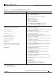
This appendix provides the following cabling and pinout information for the Cisco uBR10012 routers.
• Coaxial Cables, page B-1
• Console and Auxiliary Port Cables and Pinouts, page B-2
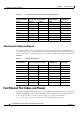
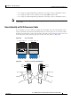
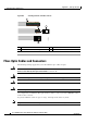
• Fast Ethernet Port Cables and Pinouts, page B-4
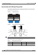
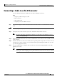
• Connecting a Cable to an RJ-45 Connector, page B-7
• Fiber-Optic Cables and Connectors, page B-8
Note This appendix specifies pinouts only for the pins used. Pins not listed in the tables are not connected.
For more information about cables and connectors, refer to the Cabling Guide for Console and AUX
Ports at the following URL:
http://www.cisco.com/en/US/products/hw/routers/ps332/products_tech_note09186a0080094ce6.shtml
Coaxial Cables
The coaxial cable used to connect the Cisco uBR10012 universal broadband routers at the headend
should be very high-quality cable.
Cisco recommends that you use a headend-grade coaxial cable or a quad-shield coaxial cable to connect
the cable
modem cards to the HFC network. The center conductor must be straight and extend 1/8 in.
(3.2 mm) beyond the end of the connector, and the connector should be securely crimped to the cable.
The following headend cables are recommended:
• 59-series cable (preferred) —20 AWG (0.032 in./0.81 mm diameter) silver plated, copper-clad, steel
center conductor; bonded foil inner shield; 95% braid second shield; non-bonded foil third shield;
95% braid fourth shield.
• 59-series quad shield—20 AWG (0.032 in./0.81 mm diameter) copper-clad steel center conductor;
bonded foil inner shield; 53% braid second shield; non-bonded foil third shield; 34%-35% braid
fourth shield.
• 6-series quad shield—18 AWG (0.0359 in./0.91 mm diameter) copper-clad steel center conductor;
bonded foil inner shield; 60% braid second shield; non-bonded foil third shield; 40%-42% braid
fourth shield.