
Universal Broadband Router Hardware Installation Guide


5-60
Cisco uBR10012 Universal Broadband Router Hardware Installation Guide
OL-18259-01
Chapter 5 Maintaining the Cisco uBR10012 Router
Removing and Replacing a Cable Interface Line Card
Removing and Replacing a Cable Interface Line Card
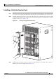
Use the following procedure to install a new cable interface line card, or to remove or replace an existing
cable interface line card in the Cisco uBR10012 chassis. The following cable interface line cards are
supported:
• Cisco uBR10-LCP2-MC16C, UBR10-LCP2-MC16C=,
• Cisco uBR10-LCP2-MC16E, UBR10-LCP2-MC16E=
• Cisco uBR10-LCP2-MC16S, UBR10-LCP2-MC16S=
• Cisco uBR10-LCP2-MC28C, UBR10-LCP2-MC28C=
• Cisco uBR10-MC5X20S/U, UBR10-MC5X20S=, UBR10-MC5X20U=
Caution Do not attempt to separate or remove the Cisco MCxx cable interface card from the Cisco uBR10-LCP2
adapter card while the cards are installed in the Cisco
uBR10012 chassis. The cards must be removed
from the chassis as a unit. See the
“Removing and Replacing the Cable Interface Line Card in the
Adapter Card” section on page 5-65.
Tip To prevent alarms from activating, you must administratively shut down a cable interface line card before
hot-swapping it. Otherwise, inform the network administrator that this portion of the network will be
temporarily interrupted. If the maintenance LED is lighted, you can remove the line card without
affecting systems operations.
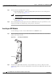
Removing the Cable Interface Line Card
Step 1 Attach an antistatic wrist strap to your wrist and to a bare metal, unpainted surface on the chassis or
frame.
Step 2 Face the back of the Cisco uBR10012 chassis. Clear aside enough interface and power cables to allow
sufficient space to work.
Step 3 If installing a new cable interface line card in a blank slot, remove the blank slot cover and discard.
Otherwise, disconnect all coaxial cables from the cable interface line card being replaced or removed.
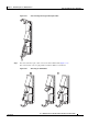
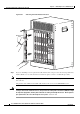
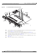
Step 4 Unscrew the top and bottom captive screws on the cable interface line card (see Figure 5-54).