
Universal Broadband Router Hardware Installation Guide

5-38
Cisco uBR10012 Universal Broadband Router Hardware Installation Guide
OL-18259-01
Chapter 5 Maintaining the Cisco uBR10012 Router
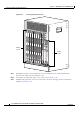
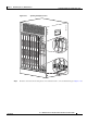
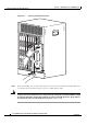
Removing and Replacing a Timing, Communication, and Control Plus Card
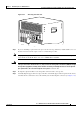
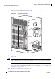
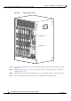
Figure 5-35 Inserting the TCC+ Card
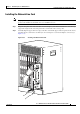
Step 10 Secure the line card in the chassis by tightening the top and bottom captive screws (see Figure 5-33).
Caution Always tighten the captive screws on each TCC+ card. These screws prevent accidental removal and
provide proper grounding for electromagnetic interference (EMI) shielding.
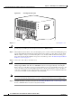
Step 11 When fully inserted, the TCC+ card cycles through its power-on self-test. The Power LED lights (green)
and the Status LED then briefly lights (yellow). If this is the primary (or only) TCC+ card, the Status
LED then lights a solid green. On the backup TCC+ card, the Status LED should start flashing green
after a few moments. If these LEDs do not operate as described, go to the
“Troubleshooting Installation
Problems” section on page 4-2.
Step 12 Connect the clock cables to the TCC+ card.
Caution The TCC+ card can connect only to a national clock source such as a GPS receiver or Building Integrated
Timing Supply (BITS) clock. The Cisco uBR10012 router does not support directly connecting the
RJ-45 connectors on the TCC+ cards to an outside plant line or telco-provided T1/E1 clock source. You
can use an outside or telco-provided T1/E1 clock source only by connecting the source to the TCC+
cards using a CSU/DSU or other equipment that is approved to FCC part 68 and ANSI/UL1950 for the
connection to the Public Switched Telephone Network (PSTN).
Note It is not necessary to configure the TCC+ card if you are installing a replacement card in the same slot.
The system automatically downloads the necessary configuration information from the PRE module.
Step 13 Configure the TCC+ card if necessary (see the “Formatting PC Media Cards” section on page 3-66, or
the Cisco uBR10012 Router Software Configuration Guide).
CISCO
10000
F
A
IL
CISCO
10000
F
A
IL
CISCO
10000
F
A
IL
CISC
100
F
A
IL
U
S
0
U
S
1
U
S
2
U
S
3
U
S
4
U
S
5
U
S
6
U
S
7
U
S
8
U
S
9
uBR10-MC5x20S-D
PO
W
E
R
STA
TU
S
M
A
INT
U
S
0
U
S
1
U
S
2
U
S
3
U
S
4
U
S
5
U
S
6
U
S
7
U
S
8
U
S
9
uBR10-MC5x20S-D
P
OW
E
R
ST
A
TU
S
M
AIN
T
U
S
0
U
S
1
U
S
2
U
S
3
U
S
4
U
S
5
U
S
6
U
S
7
U
S
8
U
S
9
uBR10-MC5x20S-D
P
OW
E
R
STA
TU
S
MA
INT
U
S
0
U
S
1
U
S
2
U
S
3
U
S
4
U
S
5
U
S
6
U
S
7
U
S
8
U
S
9
uBR10-MC5x20S-D
PO
WE
R
STA
TUS
M
AIN
T
U
S
0
U
S
1
U
S
2
U
S
3
U
S
4
U
S
5
U
S
6
U
S
7
U
S
8
U
S
9
uBR10-MC5x20S-D
PO
W
ER
ST
ATU
S
MAI
NT
U
S
0
U
S
1
U
S
2
U
S
3
U
S
4
U
S
5
U
S
6
U
S
7
U
S
8
U
S
9
uBR10-MC5x20S-D
PO
W
ER
S
TATU
S
M
AIN
T
U
S
0
U
S
1
U
S
2
U
S
3
U
S
4
U
S
5
U
S
6
U
S
7
U
S
8
U
S
9
uBR10-MC5x20S-D
PO
W
ER
S
TATU
S
MA
IN
T
U
S
0
U
S
1
U
S
2
U
S
3
U
S
4
U
S
5
U
S
6
U
S
7
U
S
8
U
S
9
uBR10-MC5x20S-D
PO
W
E
R
S
TAT
US
MA
IN
T
56458