
Universal Broadband Router Hardware Installation Guide


5-32
Cisco uBR10012 Universal Broadband Router Hardware Installation Guide
OL-18259-01
Chapter 5 Maintaining the Cisco uBR10012 Router
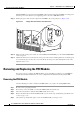
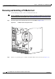
Removing and Replacing the PRE Module
Replacing the PRE Module
When replacing a PRE1 module with a PRE2 module, you must also install EMI gaskets and RF absorber
material, for more information, go to the following URL:
http://www.cisco.com/en/US/docs/cable/cmts/ubr10012/installation/field_replaceable_units/pre2gkit.h
tml
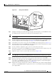
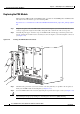
Step 1 Grasp the faceplate of the new PRE module with one hand and place your other hand under the card
carrier (to support the weight of the module) and position the card in front of the card cage slot.
Step 2 Carefully align the upper and lower edges of the PRE module with the upper and lower guides in the
chassis, and slide the module into the slot until you can feel it begin to seat in the backplane connectors
(see
Figure 5-28).
Figure 5-28 Inserting the PRE Module in the Chassis
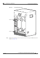
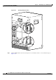
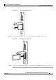
Step 3 Simultaneously pivot both ejector levers toward each other (until they are parallel to the faceplate) to
firmly seat the PRE module in the backplane (see
Figure 5-29).
Step 4 Secure the PRE module in the chassis by tightening the top and bottom captive screws (see Figure 5-25).
Caution Always tighten the captive screws on each newly installed PRE module. These screws prevent accidental
removal and provide proper grounding for electromagnetic interference (EMI) shielding.
56427
A
L
A
R
M
S
C
IS
C
O
10
0
00
F
A
I
L
PERFORMANCE ROUTING ENGINE
CONSOLE
S
T
A
T
U
S
A
C
O
C
R
I
T
I
C
A
L
M
I
N
O
R
M
A
J
O
R
ETHERNE
LINK
ACTIVITY
AUX
S
L
O
T
0
S
L
O
T
1
PERFORMANCE ROUTING ENGINE
A
LARM
S
CISCO
10000
FAIL
PERFORMANCE ROUTING ENGINE
C
O
N
S
O
L
E
STATUS
ACO
CRITICAL
MINOR
MAJOR
E
T
H
E
R
N
E
T
L
IN
K
A
C
T
IV
I
T
Y
A
U
X
S
L
O
T
0
S
L
O
T
1
POWER
MISWIRE
FAULT
POWER
MISWIRE
FAULT