
Universal Broadband Router Hardware Installation Guide


5-28
Cisco uBR10012 Universal Broadband Router Hardware Installation Guide
OL-18259-01
Chapter 5 Maintaining the Cisco uBR10012 Router
Removing and Replacing the PRE Module
The FAULT LED on each replacement AC PEM is yellow to indicate that the AC PEM is receiving power
from the power source but is not yet supplying power to the Cisco
uBR10012 chassis.
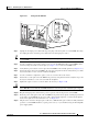
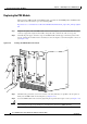
Step 13 Push up the power switch on the replacement AC PEM to the on (|) position (see Figure 5-24).
Figure 5-24 Setting AC Power Switch to the ON Position
Step 14 When you turn on the power switch on each AC PEM, its FAULT LED goes off and the POWER LED
comes on (green).
Step 15 Slide the front bezel cover onto the four corner posts of the chassis and then push down, so that the posts
are seated in the grooves above the cover holes. Route the AC power cables through the notch on the
right side of the cover.
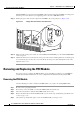
Removing and Replacing the PRE Module
It is not necessary to configure the PRE module if you are installing or replacing a second PRE. The
system automatically downloads the necessary configuration information from the primary PRE.
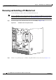
Removing the PRE Module
Use the following procedure to install a new PRE module, or to replace an existing PRE module.
Step 1 Be sure you are properly grounded.
Step 2 If necessary, remove the blank cover from the PRE module slot and discard.
Step 3 Disconnect any interface cables from the PRE module if necessary.
Step 4 Remove the PC media card from the PRE module (see the “Removing and Installing a PC Media Card”
section on page 5-34).
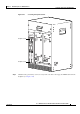
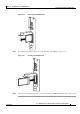
Step 5 Unscrew the top and bottom captive screws on the PRE module (see Figure 5-25).
62671
ALARM
S
FAIL
PERFORMANCE ROUTING ENGINE
STATUS
ACO
CRITICAL
MINOR
MAJOR
ALARM
S
FAIL
PERFORMANCE ROUTING ENGINE
STATUS
ACO
CRITICAL
MINOR
MAJOR
AC
SWITCH
ACINPUT
200-240V
13A 50/60Hz
AC
SW
IT
C
H
A
C
IN
P
U
T
2
00-24
0V
13A
50/60H
z
AC
SW
IT
C
H
AC
IN
PUT
200
-240V
1
3A
50/6
0H
z