
Universal Broadband Router Hardware Installation Guide


5-27
Cisco uBR10012 Universal Broadband Router Hardware Installation Guide
OL-18259-01
Chapter 5 Maintaining the Cisco uBR10012 Router
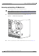
Removing and Replacing AC PEM Modules
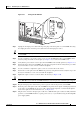
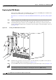
Figure 5-23 Turning the AC PEM Off
Step 3 Unplug the AC-input power cable from the power plug on the front panel of each AC PEM. For safety,
also unplug the other end of the power cable from each AC-input power source.
Tip For true redundant power protection, ensure that you are using a separate AC-input power source for
each AC PEM.
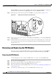
Step 4 Use the screwdriver to loosen the captive screws on each AC PEM. Then pull each AC PEM from the
chassis by using the handle on the faceplate (see
Figure 5-19). Set the two AC PEMs aside.
Step 5 Verify that the power switch on each replacement AC PEM is in the standby position (see Figure 5-23).
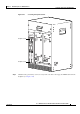
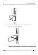
Step 6 Position the first replacement AC PEM in the power bay and push it forward. Verify that it goes all the
way in and makes a secure connection with the backplane.
Step 7 Use the screwdriver to tighten the captive screws to secure the unit to the chassis.
Step 8 Position the second replacement AC PEM in the power bay and push it forward. Verify that it goes all
the way in and makes a secure connection with the backplane.
Step 9 Tighten the captive screws to secure the unit to the chassis (see Figure 5-20).
Caution Although one AC PEM can supply sufficient power for a fully configured chassis, run the
Cisco uBR10012 router with two AC PEMs installed, because this provides redundant power support.
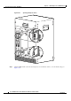
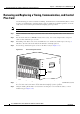
Step 10 Plug the AC-input power cable into the power receptacle on the front panel of each AC PEM.
Step 11 Route the power cable up the front of the AC PEM and clip it into the two plastic retaining clips attached
to the surface of the PEM. Route the power cable out through the right side, so that it fits through the
notch on the right side of the front bezel cover, see
Figure 5-21.
Step 12 Plug the other end of the AC-input power cable into a 200–240 VAC power outlet. For fully redundant
operation, each AC PEM should use separate power sources, or you should be using an uninterruptible
power supply (UPS).
77142
ALARM
S
FAIL
PERFORMANCE ROUTING ENGINE
STATUS
ACO
CRITICAL
MINOR
MAJOR
ALARM
S
FAIL
PERFORMANCE ROUTING ENGINE
STATUS
ACO
CRITICAL
MINOR
M
AJOR
AC
SWITCH
ACINPUT
200-240V
13A 50/60Hz
AC
SW
ITC
H
A
CIN
P
U
T
20
0-240V
13A 50/60H
z
A
C
IN
PU
T
200-24
0V
13A
50/60H
z
A
C
SW
ITC
H