
Universal Broadband Router Hardware Installation Guide


5-25
Cisco uBR10012 Universal Broadband Router Hardware Installation Guide
OL-18259-01
Chapter 5 Maintaining the Cisco uBR10012 Router
Removing and Replacing AC PEM Modules
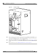
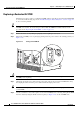
Figure 5-21 Routing the AC Power Cables
Step 10 Plug the other end of the AC-input power cable into a 200–240 VAC power outlet. For fully redundant
operation, each AC PEM should use separate power sources, or you should be using an uninterruptible
power supply (UPS).
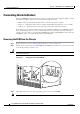
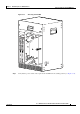
The FAULT LED on the AC PEM is yellow to indicate that the AC PEM is receiving power from the
power source but is not yet supplying power to the Cisco
uBR10012 chassis.
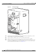
Step 11 Push up the power switch on the replacement AC PEM to the on (|) position (see Figure 5-22).
ALAR
MS
C
ISCO
10000
FAIL
PERFORMANCE ROUTING ENGINE
C
O
N
S
O
L
E
STATUS
ACO
CRITICAL
MINOR
MAJOR
E
T
H
E
R
N
E
T
L
IN
K
A
C
T
I
V
I
T
Y
A
U
X
S
L
O
T
0
S
L
O
T
1
ALAR
M
S
CIS
CO
10000
FAIL
PERFORMANCE ROUTING ENGINE
C
O
N
S
O
L
E
STATUS
ACO
CRITICAL
MINOR
MAJOR
E
T
H
E
R
N
E
T
L
I
N
K
A
C
T
IV
IT
Y
A
U
X
S
L
O
T
0
S
L
O
T
1
77143
POWER
FAULT
POWER
FAULT