
Universal Broadband Router Hardware Installation Guide


5-22
Cisco uBR10012 Universal Broadband Router Hardware Installation Guide
OL-18259-01
Chapter 5 Maintaining the Cisco uBR10012 Router
Removing and Replacing AC PEM Modules
Replacing a Redundant AC PEM
Follow this procedure to replace a redundant AC PEM, which is typically needed when the FAULT LED
is on and the troubleshooting steps in the
“Troubleshooting the Power Subsystem” section on page 4-7
do not correct the problem.
Tip If you want to replace both AC PEMs without shutting down the router, repeat this procedure for each
AC PEM, one at a time. Do not use this procedure if both AC PEMs have failed; instead, use the
procedure in the “Replacing Both DC PEMs” section on page 5-13.
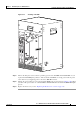
Step 1 Remove the front cover by lifting it up slightly and then pulling it toward you.
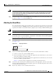
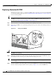
Step 2 Turn off the AC PEM you are replacing by pushing down the power switch to the standby position (see
Figure 5-18).
Figure 5-18 Turning an AC PEM Off
Caution Do not power off both AC PEMs, or the system shuts down and all data traffic stops. Power off only the
AC PEM you are replacing.
Step 3 Unplug the AC-input power cable from the power plug on the front panel of the AC PEM. For safety,
also unplug the other end of the power cable from the AC-input power source.
Tip For true redundant power protection, ensure that you are using a separate AC-input power source for
each AC PEM.
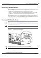
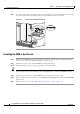
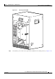
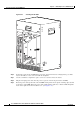
Step 4 Use the screwdriver to loosen the captive screws on the AC PEM you are removing. Then pull the PEM
from the chassis by using the handle on the faceplate (see
Figure 5-19). Set the AC PEM aside.
77142
ALARM
S
FAIL
PERFORMANCE ROUTING ENGINE
STATUS
ACO
CRITICAL
MINOR
MAJOR
ALARM
S
FAIL
PERFORMANCE ROUTING ENGINE
STATUS
ACO
CRITICAL
MINOR
MAJOR
AC
SWITCH
ACINPUT
200-240V
13A 50/60Hz
A
C
S
W
ITC
H
A
C
IN
P
U
T
200
-240V
13
A 5
0/6
0H
z
AC
INP
U
T
200-240
V
13A
50
/60
H
z
A
C
S
W
IT
C
H