
Universal Broadband Router Hardware Installation Guide


5-20
Cisco uBR10012 Universal Broadband Router Hardware Installation Guide
OL-18259-01
Chapter 5 Maintaining the Cisco uBR10012 Router
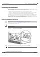
Connecting Alarm Indicators
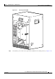
Step 5 Secure the cabling to the chassis by feeding a tie wrap through one of the round holes next to the large
hole on the side of the chassis. Then use the tie wrap to bind the cables to the chassis.
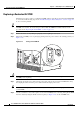
Figure 5-17 Alarm Terminal Block Connections
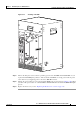
Installing the PEM in the Chassis
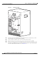
Step 1 Position the DC PEM in the power bay and push it forward, verifying that it goes all the way in and
makes a secure connection with the backplane (see
Figure 5-14).
Step 2 Tighten the captive screws on the DC PEM to lock it into the chassis.
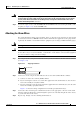
Step 3 Turn on the DC power source that are providing power for DC PEM.
Tip The FAULT LED on each replacement DC PEM lights (yellow) to indicate that the DC PEM is receiving
power from the power source but that it is not yet supplying power to the Cisco uBR10012 chassis.
Step 4 Push up the power switch on each DC PEM to the on (|) position (see Figure 5-10).
Step 5 When you turn on the power switch on each DC PEM, its FAULT LED turns off and the POWER LED
lights (green).
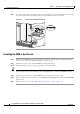
Step 6 Replace the front cover (see the “Replacing the Front Cover” section on page 5-4).
98749
ALARMS
60 VDC
1A MAX
MINOR
NC NOCOM
MAJOR
NC NOCOM
CRITICAL
NC NOCOM
MINOR
NC NOCOM