
Universal Broadband Router Hardware Installation Guide


5-18
Cisco uBR10012 Universal Broadband Router Hardware Installation Guide
OL-18259-01
Chapter 5 Maintaining the Cisco uBR10012 Router
Connecting Alarm Indicators
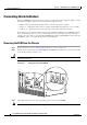
Connecting Alarm Indicators
The Cisco uBR10012 router provides relay contacts for optional (customer-supplied) audible or visual
alarm indicators. Relay contacts are provided for three levels of severity:
• Minor—This is an informational alarm and does not affect the system operation.
• Major—A condition that affects system operation and should be investigated as soon as possible.
• Critical—A condition that affects system operation and requires immediate attention.
If you did not connect the alarm indicators when you originally installed the Cisco uBR10012 chassis,
use the following procedure to connect an alarm indicator to the system. For safety and convenience
reasons, you need to remove power from the DC PEM on the right side (DC PEM “B”) and remove that
DC PEM for easier access to the alarm indicators terminal block.
Removing the PEM from the Chassis
Step 1 Remove the front cover (see “Removing the Front Cover” section on page 5-3).
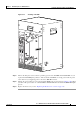
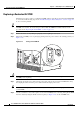
Step 2 Turn the power switch on the second DC PEM (the DC PEM on the right side, as you face the chassis)
to the off (0) position (see
Figure 5-15).
Caution Do not turn off the first DC PEM or turn off its DC power source. Otherwise, the system will
immediately shut down.
Figure 5-15 Turning the Second DC PEM Off
Step 3 Turn off the DC power source that is providing power for the second DC PEM.
Note All LEDs on the DC PEM should turn off.
56461
ALARM
S
FAIL
PERFORMANCE ROUTING ENGINE
STATUS
ACO
CRITICAL
MINOR
MAJOR
ALAR
M
S
FAIL
PERFORMANCE ROUTING ENGINE
STATUS
ACO
CRITICAL
MINOR
MAJOR
OFF
OFF
OFF