
Universal Broadband Router Hardware Installation Guide


5-17
Cisco uBR10012 Universal Broadband Router Hardware Installation Guide
OL-18259-01
Chapter 5 Maintaining the Cisco uBR10012 Router
Removing and Replacing DC Power Entry Modules
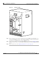
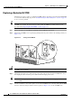
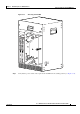
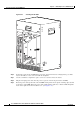
Figure 5-14 Installing a DC PEM
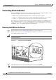
Step 11 Turn on the DC power sources that are providing power for the DC PEMs. The FAULT LED on each
replacement DC PEM lights (yellow) to indicate that the DC PEM is receiving power from the power
source but is not yet supplying power to the Cisco uBR10012 chassis.
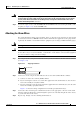
Step 12 Push up the power switch on each replacement DC PEM to the on (|) position (see Figure 5-10). When
you turn on the power switch on each DC PEM, its FAULT LED turns off and the POWER LED lights
(green).
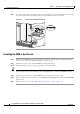
Step 13 Replace the front cover (see the “Replacing the Front Cover” section on page 5-4).
56464
POWER
MISWIRE
FAULT
ALARM
S
CIS
CO
10000
FAIL
PERFORMANCE ROUTING ENGINE
C
O
N
S
O
L
E
STATUS
ACO
CRITICAL
MINOR
MAJOR
E
T
H
E
R
N
E
T
L
I
N
K
A
C
T
IV
I
T
Y
A
U
X
S
L
O
T
0
S
L
O
T
1
ALAR
M
S
CIS
CO
10000
FAIL
PERFORMANCE ROUTING ENGINE
C
O
N
S
O
L
E
STATUS
ACO
CRITICAL
MINOR
MAJOR
E
T
H
E
R
N
E
T
L
IN
K
A
C
T
I
V
I
T
Y
A
U
X
S
L
O
T
0
S
L
O
T
1
POWER
MISWIRE
FAULT