
Universal Broadband Router Hardware Installation Guide


5-16
Cisco uBR10012 Universal Broadband Router Hardware Installation Guide
OL-18259-01
Chapter 5 Maintaining the Cisco uBR10012 Router
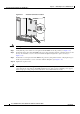
Removing and Replacing DC Power Entry Modules
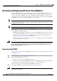
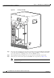
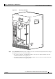
Figure 5-13 DC Power Connection Location
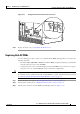
Warning
Use copper conductors only.
Statement 1025
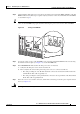
Step 7 Verify that the power switch on each replacement DC PEM is in the off position (see Figure 5-6).
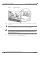
Step 8 Position the first replacement DC PEM in the power bay and push it forward, verifying that it goes all
the way in and makes a secure connection with the backplane. Tighten the captive screws (see
Figure 5-14).
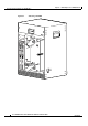
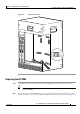
Step 9 Position the second replacement DC PEM in the power bay and push it forward, verifying that it goes
all the way in and makes a secure connection with the backplane (see
Figure 5-14).
Step 10 Tighten the captive screws.
Caution Although one DC PEM can supply sufficient power for a fully configured chassis, the Cisco uBR10012
router must be run only with two DC PEMs installed because this provides redundant power support,
allows for proper cooling, and prevents inadvertent contact with hazardous circuits.
98748
RTN (+)
–48/–60
V