
Universal Broadband Router Hardware Installation Guide


5-13
Cisco uBR10012 Universal Broadband Router Hardware Installation Guide
OL-18259-01
Chapter 5 Maintaining the Cisco uBR10012 Router
Removing and Replacing DC Power Entry Modules
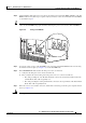
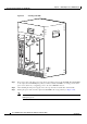
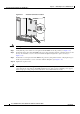
Figure 5-10 Setting the DC Power Switch to the On Position
Step 6 Replace the front cover (see “Replacing the Front Cover”).
Replacing Both DC PEMs
Use the following procedure to replace (or reinstall) both DC PEMs. This typically is done only in the
following situations:
• The failure LEDs (MISWIRE or FAULT) on both DC PEMs are lighted, indicating a problem with
either the DC power source or the DC PEMs.
• A single DC power source is currently being used for both DC PEMs, and you want to use a separate
DC power source for each DC PEM (this is the recommended configuration).
Caution This procedure requires shutting down the Cisco uBR10012 router and removing all power to the system.
To avoid this, Cisco recommends replacing each DC PEM one at a time, using the instructions given in
the “Removing and Replacing DC Power Entry Modules” section on page 5-8.
Step 1 Remove the front cover (refer to “Removing the Front Cover” section on page 5-3).
Step 2 Shut down the system (refer to “Shutting Down the System” section on page 5-2).
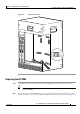
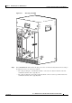
Step 3 Turn the power switch on each DC PEM to the OFF (0) position (see Figure 5-11).
56462
A
LA
RMS
FAIL
PERFORMANCE ROUTING ENGINE
STAT U
S
ACO
CR
ITICAL
MINOR
MAJOR
ALARM
S
FAIL
PERFORMANCE ROUTING ENGINE
STATUS
ACO
CRITICAL
MINOR
MAJOR
ON
ON
ON
ON
ON
ON
ON
ON
ON