
Universal Broadband Router Hardware Installation Guide


5-12
Cisco uBR10012 Universal Broadband Router Hardware Installation Guide
OL-18259-01
Chapter 5 Maintaining the Cisco uBR10012 Router
Removing and Replacing DC Power Entry Modules
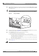
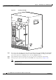
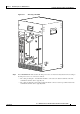
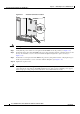
Figure 5-9 Installing a DC PEM
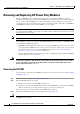
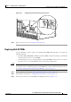
Step 3 If necessary, turn on the DC power source that is providing power for this DC PEM. The FAULT LED
on the replacement DC PEM lights (yellow) to indicate that the DC PEM is receiving power from the
power source but is not yet supplying power to the Cisco uBR10012 chassis.
Step 4 After installing the DC power supply, remove the tape from the circuit breaker switch handle.
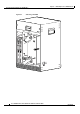
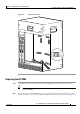
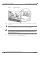
Step 5 Push up the power switch on the replacement DC PEM to the on (|) position (see Figure 5-10).
Note When you turn the power switch on, the FAULT LED on the DC PEM turns off and the POWER
LED lights (green).
56464
POWER
MISWIRE
FAULT
ALARM
S
CISCO
10000
FAIL
PERFORMANCE ROUTING ENGINE
C
O
N
S
O
L
E
STATUS
ACO
CRITICAL
MINOR
MAJOR
E
T
H
E
R
N
E
T
L
I
N
K
A
C
T
I
V
I
T
Y
A
U
X
S
L
O
T
0
S
L
O
T
1
ALAR
MS
CIS
CO
10000
FAIL
PERFORMANCE ROUTING ENGINE
C
O
N
S
O
L
E
STATUS
ACO
CRITICAL
MINOR
MAJOR
E
T
H
E
R
N
E
T
L
IN
K
A
C
T
IV
I
T
Y
A
U
X
S
L
O
T
0
S
L
O
T
1
POWER
MISWIRE
FAULT